

Views: 0 Author: Site Editor Publish Time: 2026-08-23 Origin: Site


A minor mechanical failure at a cable entry point routinely leads to catastrophic equipment downtime, electrical fires, or safety incidents. Industrial and commercial equipment faces constant dynamic loads, including heavy vibration, axial pulling, and rotational twisting. Without engineered mechanical isolation, these forces transfer directly to internal electrical terminals. This compromises system integrity and immediately voids manufacturer warranties. Selecting the correct hardware is not a generic choice but a critical engineering decision. You must evaluate solutions based on mechanical demands, environmental hazards, and strict regulatory compliance. Proper isolation ensures that external forces never reach the sensitive copper connections inside the panel. We see this constantly in the field: a poorly secured feed line gets yanked by a forklift or vibrates loose on a generator skid, causing a massive short circuit. Implementing proper Power Cable Strain Relief is the only reliable way to prevent these preventable failures and maintain operational safety.
The baseline expectation for power connections is zero transfer of external mechanical force to internal conductors. When external forces bypass the enclosure entry point and reach the internal terminals, failure becomes inevitable. We design systems to isolate the termination block completely. If you pull the exterior jacket, the interior wires should not move a single millimeter.
Three primary mechanical forces act on power lines in the field: axial pull (tension), rotational twist (torsion), and repetitive bending (flexing). Tension occurs when someone trips over a cord or a machine moves beyond its slack limit. Torsion happens during installation or when equipment rotates, twisting the internal copper strands until they snap. Flexing degrades the jacket and insulation over thousands of cycles.
Many contractors mistakenly believe stationary equipment is immune to mechanical stress. This is false. Installation routing, routine maintenance movement, thermal expansion, and accidental impacts still necessitate robust protection. A heavy gauge feed dropping 20 feet from a ceiling tray exerts constant gravitational tension on the terminal block. Without proper support, the copper slowly creeps out of the lug.
Failure does not happen instantly. It progresses through micro-arcing, increased electrical resistance, localized heating, and eventual terminal pull-out or a dead short. When strands break, the remaining intact strands carry the full current load. This causes them to overheat, melting the surrounding insulation.
The business risks are severe. You face equipment damage, production line halts, and operator safety hazards like shock and fire risks. A single pulled wire touching a grounded metal enclosure can trigger a massive arc flash if the breaker does not trip fast enough.
| Failure Stage | Physical Symptom | Operational Consequence |
|---|---|---|
| Initial Stress | Jacket pulls back from the connector | Loss of environmental seal, moisture ingress |
| Strand Breakage | Internal copper strands snap | Increased resistance, localized heating |
| Insulation Melt | Discolored or melted wire insulation | High risk of cross-phasing or grounding |
| Terminal Pull-Out | Wire completely detaches from lug | Total power loss, potential arc flash |
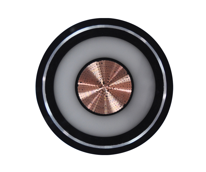
Properly engineered entry points directly offset operational risks and maintenance costs. You spend a few extra dollars on a quality gland to protect a motor worth tens of thousands of dollars.
Securing the jacket prevents live wires from contacting metal enclosures if a terminal connection fails. If a wire does break loose, the mechanical grip holds the assembly in place, preventing the energized conductor from whipping around inside the panel. This is a fundamental safety requirement in any industrial control panel.
Proper hardware also maintains grounding path integrity in high-vibration environments. If the ground wire vibrates loose because the main feed is not secured, the entire machine becomes a shock hazard. Mechanical isolation ensures the ground lug remains torqued to specification.
Distributing mechanical loads over a larger surface area reduces point-stress on the jacket. When you clamp down on a wide section of the outer sheath, you prevent the internal wires from taking the brunt of the force. This maximizes the lifespan of both the assembly and the internal connectors.
We use specific cable bend protection devices on moving machinery to ensure the bend radius never exceeds the manufacturer's limits. Forcing a thick feed to bend sharply at the enclosure entry will crack the insulation within months. A proper flex-nut or spiral guard forces a gentle sweep, extending the service life by years.
Major standards like UL 62, UL 514B, and IEC 62444 dictate strict testing requirements for entry hardware. Inspectors will fail a panel if they see feed lines passing through sharp metal knockouts without proper securing mechanisms. Failing to specify compliant hardware exposes manufacturers and facility operators to compliance failures and liability during safety audits.
Market options vary wildly. Selecting the right one depends entirely on your specific application requirements, environmental exposure, and mechanical load.
These utilize compression nuts and elastomeric seals gripping the jacket. As you tighten the dome nut, internal fingers compress a rubber seal tightly around the sheath. They are best for enclosures requiring simultaneous mechanical grip and environmental sealing against dust and water at the equipment panel interface.
We use these extensively on outdoor junction boxes and washdown-rated food processing equipment. They provide excellent IP68 or IP69K protection while ensuring the feed line cannot be yanked out of the terminal block.
Woven wire mesh tightens its grip as tension increases. Often called Kellums grips, these devices work like a Chinese finger trap. The harder you pull, the tighter the mesh squeezes the jacket. These are ideal for overhead drops, heavy portable equipment, and applications requiring extreme pull-out resistance.
If you have a pendant station hanging from a crane, you must use a wire mesh grip. A standard plastic gland will strip the jacket under the constant hanging weight. The mesh distributes the load over a foot or more of the cord, preventing localized crushing.
Permanently overmolded polymers integrate directly into the cordset during manufacturing. They are best for consumer electronics, medical devices, and applications requiring highly controlled flex characteristics and aesthetic integration. You cannot install these in the field; they must be specified during the OEM design phase.
Molded designs offer superior protection against repetitive bending. The tapered design gradually decreases stiffness, ensuring the cord bends in a smooth arc rather than a sharp angle right at the plug body.
Simple mechanical barriers lock into panel cutouts. True mechanical isolation resists axial pulling forces, while basic routing grommets only provide edge chafing protection. Snap-in bushings are best for internal wire routing or low-risk, static environments where primary pull-out forces are negligible.
Do not use a snap-in bushing as a primary securing method for an external feed. They will pop out of the panel under moderate tension. Use them only to protect wires passing through internal sheet metal bulkheads.
Engineers and buyers must match features to desired outcomes. You cannot just grab whatever fits the knockout hole. You must evaluate the material, the load, and the exact dimensions.
Evaluate material trade-offs carefully. Nylon works well for general purpose, lightweight applications. Nickel-plated brass provides excellent durability and EMI shielding for industrial drives. Stainless steel is mandatory for corrosive environments, marine applications, and chemical washdown areas.
Match the IP rating to the enclosure's rating to maintain system-level environmental integrity. Installing an IP54 gland on an IP67 enclosure downgrades the entire system to IP54. Water will enter through the gland during a washdown.
| Material Type | Best Application Environment | Key Advantage |
|---|---|---|
| Nylon / Polyamide | Indoor, general industrial, control panels | Cost-effective, lightweight, corrosion resistant |
| Nickel-Plated Brass | Heavy machinery, VFDs, outdoor enclosures | High mechanical strength, EMI/RFI shielding |
| Stainless Steel (316) | Food processing, marine, chemical plants | Extreme corrosion resistance, withstands harsh washdowns |
| PVDF / Teflon | High temperature, aggressive chemical areas | Exceptional chemical inertness and heat tolerance |
Calculate required pull-out resistance based on cord weight and expected handling abuse. If a 50-foot heavy-duty extension cord hangs vertically, the grip must support the entire weight of that copper without slipping. Evaluate the necessity of spiral or flex-nut additions for dynamic applications requiring continuous motion without kinking.
For robotics or CNC drag chains, standard glands fail quickly. You need specialized continuous-flex hardware that moves with the machine without pinching the internal conductors.
Matching the clamping range to the exact outer diameter (OD) of the sheath is critical. If the OD is 12mm, you need a gland rated for 10-14mm. If you use a gland rated for 14-18mm, the rubber seal will not compress enough to grip the jacket, resulting in zero mechanical isolation.
Using non-circular profiles with standard round hardware requires specialized inserts. If you run a flat festoon line through a round gland, water will pour through the gaps. Always specify the correct multi-hole or flat-profile elastomeric seal.
Common installation errors routinely negate the benefits of expensive hardware. I have seen thousands of dollars of equipment destroyed because an installer used a pair of channel locks instead of a torque wrench.
Applying excessive torque to compression nuts crushes the insulation and creates internal shorts. When you overtighten a plastic gland, the internal fingers bite through the outer sheath and pierce the copper conductors. Utilize torque wrenches during installation and adhere strictly to manufacturer torque specifications.
Specifying a clamping range slightly too large for the OD results in zero actual grip. The installation might look secure, but a light tug will pull the wires right out of the terminals. Implement strict incoming quality control on OD tolerances. Manufacturers sometimes change jacket thickness without changing the part number. Verify the OD with calipers before ordering the entry hardware.
Field installers often discard supplied hardware due to difficult fitment. If the supplied gland is too tight, they might just run the wire through the bare knockout, leaving the connection completely unprotected. Standardize cable strain relief design specifications across procurement and installation teams. Ensure supplied hardware matches field-deployed dimensions seamlessly.
Elastomeric seals degrade over time due to UV exposure, ozone, or chemical contact. A rubber seal that was watertight on day one might crack and leak after three years in the sun. Establish preventative maintenance schedules to inspect high-stress connection points. Specify UV-resistant or chemically inert materials like FKM or Viton upfront for harsh environments.
Mechanical isolation at the enclosure entry is a fundamental requirement for electrical safety, equipment longevity, and standard compliance. You cannot cut corners on these components without risking catastrophic failure. Choose wire mesh for high tension, overmolded for high-flex OEM cords, and metallic glands for harsh industrial environments.
A: It isolates electrical terminations from mechanical stress like pulling, twisting, and bending. By anchoring the outer jacket to the enclosure, it prevents external forces from reaching the internal copper connections, eliminating pull-outs and short circuits.
A: Evaluate the mechanical load, environmental exposure, and flex cycle requirements. Ensure the clamping range exactly matches the outer diameter. Use metallic glands for industrial impacts, nylon for general use, and wire mesh for heavy hanging loads.
A: Yes. Installation routing, routine maintenance, thermal expansion, and accidental impacts introduce mechanical stress. Even minor vibrations from nearby machinery can degrade unsecured connections over time, leading to increased resistance and failure.
A: Yes, certain designs like compression glands use elastomeric seals to provide ingress protection. When properly torqued, they can achieve IP68 or IP69K ratings, completely blocking dust, water, and chemical washdowns from entering the enclosure.
A: A gland uses a threaded compression nut and rubber seal for fixed anchoring and environmental sealing. A wire mesh grip tightens its woven metal mesh around the jacket under tension, distributing heavy loads over a larger area for portable equipment.
A: Bend protection specifically prevents repetitive flexing from kinking or damaging the jacket. It utilizes spiral extensions, flex-nuts, or tapered molded designs to enforce a minimum bend radius, whereas standard hardware only prevents axial pull-out.
 简体中文
简体中文 

