

Views: 0 Author: Site Editor Publish Time: 2026-08-09 Origin: Site


An Elevator Traveling Cable operates as a highly specialized, flexible multi-conductor lifeline. It acts as the critical, continuously moving umbilical cord connecting stationary building control systems to the moving elevator car. While fixed wiring handles static power distribution throughout a facility, the traveling cable manages constant motion, severe mechanical stress, and complex signal transmission simultaneously.
Traveling cable degradation presents severe operational risks for any facility. Unnoticed wear in this continually-in-motion component leads to intermittent signal loss, unexpected downtime, and safety code violations. Eventually, compromised cables force costly emergency replacements that disrupt building operations. Facility managers and modernization engineers need a technical framework for evaluating and specifying replacement cables based on mechanical requirements and modern data needs.
The cable must achieve flawless transmission under continuous mechanical stress without compromising electrical integrity at any point during operation. This multi-conductor lifeline bridges the fixed building infrastructure and the moving car. It bends, flexes, and hangs under its own weight thousands of times a day. Standard static building wire would fail within days in this harsh dynamic environment.
Traveling cables evolved significantly over the past few decades. Early versions functioned as simple power transmitters for basic cab lighting and motor operation. Today, they serve as complex, multi-functional hubs. Smart elevators require high-speed data, video feeds, and precise control signaling to operate safely and efficiently.
Modern elevator systems demand distinct transmission capabilities from a single suspended bundle. Each function requires specific conductor sizing, stranding, and shielding to prevent interference.
Engineers design every layer of the cable to withstand dynamic hoistway conditions. The materials chosen dictate the flexibility, durability, and safety of the installation.
When evaluating the anatomy of a replacement cable, you must verify the exact specifications of the strain relief core. A steel core provides maximum tensile strength for high-rise applications, while aramid fibers offer a lighter alternative for medium-rise installations where weight reduction is necessary.
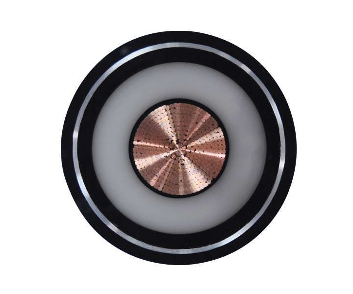
Facility managers must choose between two primary structural designs. This choice serves as the foundation for your cable selector guide. Each geometry fits specific architectural and mechanical use cases based on the hoistway dimensions and elevator mechanics.
Flat cables feature conductors laid parallel in a single plane. This arrangement creates a wide, ribbon-like profile. The design allows the cable to bend easily along one specific axis, making it highly predictable in its movement pattern.
These cables are ideal for low-to-medium rise buildings. Hydraulic elevators frequently utilize flat designs. Installations with tight hoistway clearances benefit greatly from the slim profile. The flat shape requires less operational space behind the car, allowing for more compact hoistway designs.
There are distinct trade-offs to consider. Flat cables offer superior flexibility in a single bending axis. Technicians find them easier to visually inspect for damage since all conductors are visible along the flat plane. However, they are highly susceptible to wind sway. High-rise applications generally avoid flat cables due to aerodynamic instability and the risk of the cable catching on hoistway protrusions.
Circular designs bundle conductors concentrically around a central strain-bearing core. This creates a traditional cylindrical shape. The internal geometry balances the mechanical load evenly across the entire structure, preventing any single conductor from bearing excessive tension.
High-speed, high-rise traction elevators rely almost exclusively on round cables. The structural integrity supports massive hanging weights. These environments demand cables that resist twisting under extreme vertical tension and rapid acceleration.
Round cables provide a better aerodynamic profile. They offer excellent resistance to twisting and torsion during high-speed travel. The trade-off involves space and hardware. Round cables require larger bending radii. They also need more complex termination hardware to secure the internal steel core properly.
| Feature | Flat Traveling Cable | Circular (Round) Traveling Cable |
|---|---|---|
| Profile | Ribbon-like, parallel conductors | Cylindrical, concentric conductors |
| Best Application | Low-to-medium rise, hydraulic | High-rise, high-speed traction |
| Flexibility | Excellent on a single axis | Requires larger bending radius |
| Aerodynamics | Poor (susceptible to wind sway) | Excellent (resists hoistway drafts) |
| Space Requirement | Minimal clearance needed | Requires more hoistway space |
Matching multi-conductor cable specifications to current cab technology is critical. You must also anticipate future requirements. Modernization projects fail when the new cable lacks the necessary data bandwidth or low-voltage support for upcoming technology upgrades.
Engineers must segregate high-voltage power from sensitive data lines. Electromagnetic interference (EMI) disrupts video feeds and corrupts sensor data. Proper internal shielding within the cable bundle prevents this interference and ensures clean signal transmission.
Modern cabs require specific low-voltage lines. Specifying a dedicated 12V DC power cable within the bundle is highly recommended. This reliably powers modern cab accessories like LED displays, biometric scanners, and card readers. It eliminates the need for bulky, heat-generating in-cab transformers. Direct low-voltage routing improves overall system efficiency and reduces the risk of localized power failures inside the cab.
The industry is shifting away from standard twisted pair wiring. High-bandwidth IP cameras and IoT predictive maintenance sensors require more robust solutions. Coaxial and fiber optic integrations are becoming standard in new installations to handle massive data loads.
Integrating fragile fiber optics into continually moving cables presents mechanical challenges. You must evaluate bend-radius limitations strictly. Fiber strands require specialized mechanical protections within the jacket. Excessive bending or sudden acceleration will snap unprotected glass fibers, causing instant data loss. Manufacturers often encase these fibers in protective gel-filled tubes to absorb mechanical shock.
Analyzing durability and maintenance requirements helps you understand the true value of your infrastructure. Proactive evaluation prevents unexpected elevator shutdowns and extends the operational life of your equipment.
The industry-standard 20-year lifespan is a baseline, not a guarantee. Many cables fail well before this mark. The 20-year figure assumes ideal operating conditions, perfect installation, and moderate usage rates.
Environmental wear factors drastically reduce this timeline. Extreme temperature fluctuations degrade polymer jackets, causing them to become brittle. High humidity causes internal oxidation if the jacket breaches. Hoistway drafts create constant sway, accelerating mechanical fatigue. Chemical exposure from rail lubricants and cleaning agents breaks down the outer insulation prematurely.
Travel speed directly impacts the cable's flex life. Rapid acceleration and deceleration rates put immense strain on the internal core. Sheave friction wears down the outer jacket over millions of cycles, eventually exposing the internal conductors.
Improperly installed cables often experience "corkscrewing." This torsional strain occurs when technicians fail to relieve built-up tension during installation. The cable twists upon itself, forcing internal conductors to break through the outer jacket and short circuit against the hoistway walls.
Do not wait for a complete failure. Regular diagnostics reveal when a cable has reached the end of its safe operational life. Implement a strict inspection schedule.
Navigating the complexities of sourcing and installation requires a structured approach. Use a selector matrix to mitigate implementation risks and ensure code compliance.
Replacement cables must meet strict code compliances. You must adhere to NEC Article 620, EN 81, or CSA B44 depending on your region. These codes dictate flame retardancy and smoke emission standards. They also enforce strict electrical safety parameters for moving hoistway equipment to prevent fire hazards.
Technicians must "pre-stretch" or hang the cable prior to final termination. This process allows the cable to relax and prevents operational twisting. Skipping this step guarantees premature corkscrewing and rapid mechanical failure.
Installation requires specialized suspension hardware. Kellems grips or wedge clamps must match the cable's exact weight and geometry. The hardware must support the specific multi-conductor payload without crushing the internal fiber optics or deforming the outer jacket.
A full replacement involves significant labor costs and elevator downtime. You must plan for a multi-day outage. Splicing a damaged traveling cable is not a viable long-term solution. Codes generally prohibit splicing for safety and structural reasons. Full replacement remains the only compliant fix.
| Installation Step | Critical Action | Risk of Failure |
|---|---|---|
| Pre-stretching | Hang cable freely for 24-48 hours | Severe corkscrewing and torsion |
| Hardware Selection | Match grip to exact cable diameter | Crushed internal fiber optics |
| Loop Adjustment | Set correct bottom loop clearance | Cable snagging on pit equipment |
| Termination | Secure strain relief core properly | Conductors bearing physical weight |
The elevator traveling cable is a highly engineered, continually moving component critical to safety and uptime. Selecting the wrong cable compromises your entire vertical transportation system and leads to rapid mechanical failure.
Match your cable geometry to the building height and elevator speed. Match the conductor payload to your current and future data needs. Ensure your specifications include necessary low-voltage lines for modern technology upgrades.
Take the following steps to secure your elevator infrastructure:
A: The industry-standard baseline lifespan is 20 years. However, this is an average under ideal conditions. Mechanical factors like high travel speeds and rapid acceleration reduce longevity. Environmental factors, including extreme temperatures, humidity, hoistway drafts, and chemical exposure, also significantly shorten the cable's actual operational life.
A: Flat cables are used primarily in low-to-medium rise buildings and hydraulic elevators. Their ribbon-like design requires minimal hoistway clearance behind the car. They offer excellent flexibility along a single bending axis. However, they are susceptible to wind sway, making them unsuitable for high-rise, high-speed applications.
A: No, repairing or splicing a damaged traveling cable is not standard practice. Safety codes generally prohibit splicing because it compromises the cable's structural integrity and electrical shielding. A spliced cable cannot safely withstand the continuous mechanical stress of hoistway movement. Full replacement is required.
A: Security cameras require dedicated, shielded lines within the cable bundle to prevent electromagnetic interference from high-voltage power. Depending on the camera system, manufacturers integrate coaxial cables, shielded twisted pairs, or specialized fiber optic strands directly into the traveling cable to ensure high-bandwidth, uninterrupted video transmission.
A: A 12V DC line provides direct, reliable power for modern, low-voltage cab accessories. It powers card readers, biometric scanners, emergency lighting, and digital screens. Integrating this specific line eliminates the need for bulky, heat-generating transformers inside the elevator car, improving efficiency and reducing interference.
A: Corkscrewing is primarily caused by improper installation. If technicians fail to "pre-stretch" or hang the cable to let it relax before termination, built-up torsional tension remains. Over time, continuous vertical movement forces the cable to twist upon itself. Failure of the internal strain relief core also causes corkscrewing.
 简体中文
简体中文 

