

Views: 0 Author: Site Editor Publish Time: 2026-08-06 Origin: Site


Signal integrity dictates the heartbeat of automated industrial environments. A single dropped command or corrupted data packet halts production lines, damages equipment, and compromises worker safety. Specifying inadequate cabling for harsh environments introduces severe operational risks. Premature mechanical failure, electromagnetic interference, and chemical degradation lead to unplanned downtime and hazardous conditions. Engineers and procurement teams must apply a rigorous technical evaluation framework. You need to match specific architectures to exact application requirements. We will break down how to evaluate and select the right wiring for your facility, moving past basic definitions into practical field application.
The fundamental construction relies on finely stranded copper conductors, specialized insulation, and a protective outer jacket. Fine stranding provides the flexibility needed for routing through tight panel spaces and enduring dynamic machine movements. Insulation materials are selected based on dielectric strength and resistance to specific environmental factors found on the factory floor.
These lines transmit low-voltage signals and power, typically operating within the 300V to 600V range. You will find them carrying 24V DC or 120V AC between programmable logic controllers (PLCs), relays, switches, and automated machinery. They act as the nervous system of an automated process. They deliver discrete commands to actuators and return analog or digital sensor feedback to the main processor.
Deployment spans across diverse and punishing industrial environments. In robotic assembly facilities, they manage complex multi-axis movements where continuous flexing is mandatory. Metal fabricating plants rely on them for precise machine tool operation amidst flying debris and cutting fluids. Wastewater treatment centers use them to control pumps and monitor fluid levels in highly corrosive atmospheres.
These lines play a vital role in closed-loop feedback systems. They transmit sensor data back to controllers, allowing for real-time adjustments to motor speeds and valve positions. Specialized use cases include pendant controls for overhead cranes and hoists. These overhead applications require unique strain-relief architectures. Manufacturers incorporate steel support members or aramid yarns to bear the weight of the suspended run, preventing the copper conductors from stretching and breaking.
The primary distinction lies in electrical load capacity and conductor sizing. Power lines are built for high-amperage, heavy-gauge requirements. They carry the primary electrical energy needed to drive large motors, industrial heaters, and heavy machinery. Their conductors are thick, prioritizing current-carrying capacity and thermal dissipation over physical flexibility.
Conversely, the multi-conductor design focuses on low-amperage transmission. While they do not drive heavy machinery directly, they are essential for powering the low-voltage end-devices that dictate machine behavior. They provide the necessary voltage to operate sensors, actuators, and relays. The engineering focus remains on signal integrity and managing multiple discrete circuits within a single, flexible jacket.
These multi-core lines interact seamlessly within a facility's electrical ecosystem. They bridge the gap between the high-power infrastructure and the sensitive control logic. Proper integration ensures that commands from the PLC are executed accurately by the field devices without delay or distortion.
Furthermore, they are frequently utilized to relay diagnostic data for power cable monitoring systems. By transmitting temperature, vibration, or partial discharge data from sensors attached to high-voltage lines, they help ensure facility-wide electrical health and prevent catastrophic power failures before they occur.
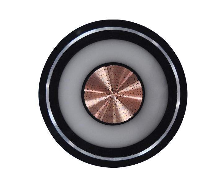
The choice between shielded and unshielded configurations depends entirely on the electromagnetic environment of your facility. Unshielded variants are suitable for environments with minimal electrical noise. They are easier to strip, terminate, and route, but they offer zero protection against external interference.
Foil shielding provides baseline protection against high-frequency EMI. It consists of a thin layer of aluminum or copper foil wrapped around the conductor bundle. Braid shielding, typically made of copper or tinned copper, offers superior physical durability and low-frequency EMI protection. Braid shielding is mandatory for environments with heavy motor drives, variable frequency drives (VFDs), or welding equipment.
| Shielding Type | Primary Protection | Flexibility | Best Application |
|---|---|---|---|
| Unshielded | None | High | Clean environments, basic relay logic |
| Foil Shield | High-Frequency EMI | Medium | Static routing near minor noise sources |
| Tinned Copper Braid | Low-Frequency EMI & Physical Impact | Medium-Low | VFD environments, heavy machinery |
| Foil + Braid | Broadband EMI | Low | Severe noise environments, servo motors |
Understanding regional naming conventions is necessary for global procurement and compliance. European standards often use a two-letter designation. YY indicates unshielded, general-purpose lines. SY incorporates a steel wire braid for mechanical protection, making it suitable for harsh physical environments. CY features a copper braid specifically for EMI protection.
North American equivalents follow different naming structures tied to installation methods. VNTC (Tray Cable) is a common designation for lines rated for use in standard cable trays. TC-ER (Exposed Run) indicates a line that meets stringent crush and impact tests. PLTC (Power-Limited Tray Cable) is used strictly for lower voltage, power-limited circuits.
Physical movement requirements dictate the mechanical design. Static lines are designed for fixed installations, such as routing through rigid conduit or standard trays. They use standard Class B or Class C stranding and jacket materials optimized for stationary environments.
Continuous flex lines are engineered for dynamic motion applications, such as drag chains and multi-axis robotics. They utilize ultra-fine Class 6 stranding and specialized jacket materials like PUR to withstand millions of flex cycles without conductor breakage. Pendant and festoon lines are specialized designs incorporating load-bearing elements to support their own weight in overhead applications.
Evaluating jacket materials based on exposure risks is the first step in specification. PVC is a common choice for general-purpose indoor applications. However, PVC degrades rapidly when exposed to synthetic cutting oils or extreme temperatures. PUR offers excellent abrasion and oil resistance, making it ideal for CNC machining centers and dynamic applications. TPE provides extreme temperature and chemical resistance for the harshest environments.
You must also consider specific environmental factors. UV resistance is necessary for outdoor routing to prevent the jacket from cracking under sunlight exposure. Halogen-free (LSZH) requirements are critical for confined spaces or public infrastructure. These materials emit minimal smoke and zero toxic halogens in the event of a fire.
Defining success criteria for dynamic applications requires careful calculation. You must determine the minimum bend radius, which dictates how tightly the line can be bent without damaging the conductors or shield. Torsional stress tolerance is vital for robotic applications where the line twists along its longitudinal axis.
Expected cycle life is a key metric for continuous flex applications. Manufacturers provide data on how many millions of cycles a line can endure under specific bend radii and speeds. Matching the mechanical ratings to the machine's exact movement profile prevents premature failure.
Establishing the electrical framework ensures signal integrity. Determine the necessary voltage ratings based on the connected devices. Select the appropriate AWG sizing to handle the required current without excessive voltage drop over long runs.
Capacitance limits are critical for preventing signal attenuation. High capacitance distorts digital signals and reduces the bandwidth of analog signals. Choosing a Control Cable with low-capacitance insulation materials like XLPE is necessary for maintaining signal fidelity over extended distances.
Adherence to industry standards ensures safety and legal compliance. UL listings verify that the product has been tested for safety and performance under specific conditions. The NEC dictates installation practices in the United States. Article 336 covers the use of Power and Control Tray Cables.
CE marking is mandatory for equipment exported to the European Economic Area. It indicates conformity with health, safety, and environmental protection standards. Specifying products with the correct certifications prevents installation delays and ensures the system passes local inspection.
A TC-ER rating significantly impacts your installation strategy. This rating indicates that the product has passed severe crush and impact tests, equivalent to metal-clad armor. Consequently, the NEC allows TC-ER lines to be routed outside of a conduit or tray for a specified distance between the tray and the utilization equipment.
This flexibility reduces installation labor and material requirements. It eliminates the need for rigid conduit drops, simplifying the wiring process and allowing for easier maintenance and modifications in the future.
Improper installation introduces significant field risks. Exceeding the maximum pull tension during installation stretches the copper conductors, altering their electrical properties or causing outright breakage. Violating the minimum bend radius stresses the insulation and shielding, leading to jacket rupture and short circuits.
Improper grounding of shields is a common source of EMI issues. Shields must be terminated correctly, typically at one end only, to prevent ground loops. Following manufacturer guidelines for routing, tension, and termination is critical for long-term reliability.
Running low-voltage lines parallel to high-voltage power lines creates a high risk of cross-talk and signal degradation. The electromagnetic fields generated by the power lines induce noise into the adjacent circuits. This noise corrupts data and causes erratic machine behavior.
Mitigation strategies include maintaining physical separation distances between power and signal lines. When they must cross, they should do so at strict right angles. Utilizing twisted pair configurations and appropriate shielding further reduces the susceptibility to induced noise.
Specifying wiring requires analyzing performance trade-offs. The upfront investment in continuous-flex, highly shielded PUR lines is higher than standard PVC lines. However, using standard PVC lines in high-stress, dynamic environments guarantees rapid failure.
The long-term replacement labor and unplanned downtime far exceed the initial savings of under-specifying the product. Accurate specification involves balancing the upfront requirements with the necessary mechanical and electrical performance to ensure continuous operation.
Follow these steps to finalize your specification and ensure reliable field operation:
A: Control lines typically handle higher voltages (300V-600V) and larger AWG sizes to operate relays and contactors. Instrumentation lines are designed for very low voltage, low-current analog signals (like 4-20mA sensors) and prioritize low capacitance and individual pair shielding to maintain strict signal fidelity.
A: While they do not carry heavy loads for driving large motors, they routinely carry low-voltage power (e.g., 24V DC or 120V AC) to operate switches, relays, sensors, and actuators within the circuit.
A: No. Standard lines use rigid stranding that will quickly fatigue and break under continuous motion. Drag chains require continuous flex lines engineered with ultra-fine stranding and specialized jackets to withstand millions of bending cycles.
A: Automated machinery requires controlling multiple discrete functions, relays, and sensors simultaneously. Multi-conductor designs allow engineers to route all necessary circuits through a single, manageable run rather than pulling dozens of individual wires.
A: TC-ER stands for Tray Cable - Exposed Run. It indicates the line passes strict crush and impact tests, allowing it to be legally routed outside of a conduit or cable tray for short distances, significantly reducing installation labor.
A: To prevent ground loops, a shielded line should typically be grounded at one end only, usually at the main panel or source. The drain wire or shield braid must be securely terminated to the grounding busbar according to the manufacturer's instructions.
A: The maximum distance depends on voltage drop, capacitance, and signal attenuation. For digital signals, high capacitance over long runs distorts the signal. For power circuits, long runs require larger AWG sizes to prevent excessive voltage drop at the end device.
 简体中文
简体中文 

