

Views: 0 Author: Site Editor Publish Time: 2026-08-09 Origin: Site


An AC Power Cable serves as the critical physical link between facility power grids and sensitive hardware. Underspecified or non-compliant power cables introduce massive operational risks. Utilizing the wrong cable leads directly to thermal hardware failure, facility fires, and catastrophic system downtime. Matching hardware power requirements with correct physical infrastructure involves navigating varying global standards, environmental hazards, and strict load capacities. Engineers must evaluate wire gauge, jacket materials, and connector types to ensure safe power delivery. A mismatched connector or inadequate wire gauge creates immediate thermal hazards under peak loads. This technical evaluation guide equips IT, engineering, and procurement professionals with the necessary frameworks to accurately specify the correct power delivery components. You will learn how to evaluate conductor composition, understand the critical differences between alternating and direct current cables, and select the appropriate standardized connectors for enterprise, industrial, or specialized environments.
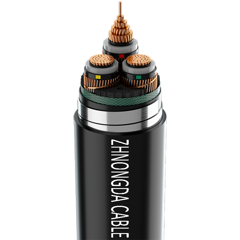
The core of any power cable relies on highly conductive metals, predominantly copper. Manufacturers utilize stranded copper for applications requiring flexibility. Stranded configurations consist of multiple thin copper wires bundled together. This design significantly improves the bend radius and prevents metal fatigue during installation. Solid core conductors offer lower electrical resistance over long distances but lack the necessary flexibility for dynamic environments. Higher strand counts directly correlate with increased durability and flexibility in tight server racks or moving machinery. When routing cables through complex cable trays or articulated arms, high-strand-count copper prevents internal breakage that would otherwise lead to localized heating and eventual failure.
Field installations often reveal the limitations of solid core wire. If a technician repeatedly bends a solid core cable to fit behind a dense server rack, the copper work-hardens and snaps. Stranded wire absorbs this mechanical stress. The exact strand count varies by application, with highly flexible robotic cables utilizing hundreds of microscopic copper strands to maintain continuity during constant motion.
Insulation surrounds each individual conductor to prevent short circuits and manage thermal output. Engineers design this internal color-coded insulation to withstand specific peak voltages. The color coding strictly identifies the Hot, Neutral, and Ground wires according to regional electrical codes. The dielectric strength of this material determines the maximum voltage the cable can handle before the insulation breaks down. High-quality thermoplastic or elastomer insulation ensures the current remains safely contained within the conductor path.
Insulation thickness directly impacts the cable's voltage rating. A 300V-rated cable features thinner insulation than a 600V-rated cable. Using a 300V cable on a 480V circuit guarantees dielectric breakdown, resulting in an arc fault. Furthermore, insulation materials must resist thermal degradation. As current flows, the conductor heats up. The insulation must withstand this internal heat without melting or becoming brittle over its operational lifespan.
Electromagnetic Interference (EMI) and Radio Frequency Interference (RFI) severely disrupt sensitive electronics. Shielding mitigates these external disruptions. Manufacturers wrap the internal conductors in aluminum foil or braided copper shielding. Foil shielding provides 100% coverage against high-frequency noise. Braided shielding offers superior structural integrity and low-frequency interference protection. This shielding is critical in dense server racks and industrial floors. When powering precision test and measurement instruments, unshielded cables allow electromagnetic waves to distort critical data.
In industrial environments featuring heavy motor loads or variable frequency drives (VFDs), electrical noise is a constant threat. An unshielded power cable acts as an antenna, broadcasting this noise to adjacent data cables. Implementing shielded power cables, properly grounded at the source, contains this interference. The shield captures the stray electromagnetic energy and shunts it safely to ground before it can affect nearby equipment.
The outer jacket serves as the primary defense against environmental hazards. This protective layer provides mechanical protection against physical abrasion, crushing, and cutting. Outer jackets also deliver environmental sealing against moisture, industrial chemicals, and UV degradation. The specific polymer blend dictates the cable's operational temperature range and overall lifespan in harsh conditions.
Polyvinyl Chloride (PVC) jackets dominate indoor IT environments due to their cost-effectiveness and adequate flexibility. However, PVC becomes brittle in freezing temperatures and degrades rapidly when exposed to industrial oils. For harsh environments, thermoset rubber or polyurethane jackets provide superior resistance to mechanical abuse and chemical exposure. Selecting the wrong jacket material leads to premature cracking, exposing the internal conductors to moisture and creating severe shock hazards.
Alternating current phase cycles continuously reverse direction at a specific frequency, typically 50Hz or 60Hz. This oscillation allows efficient long-distance power transmission. Conversely, a DC Power Cable handles a continuous, unidirectional flow of electrical charge. The physical design of the conductors and insulation must account for these fundamental differences in current flow dynamics.
The continuous reversal of alternating current creates unique stresses on the cable infrastructure. The magnetic fields surrounding the conductors constantly expand and collapse, inducing eddy currents and potential vibration in loose installations. Direct current systems maintain a steady magnetic field, eliminating these specific mechanical and electrical stresses but introducing different challenges regarding arc suppression.
Voltage rating requirements differ drastically between the two current types. Alternating current systems experience peak voltages that significantly exceed their Root Mean Square (RMS) nominal ratings. An alternating current cable must feature insulation rated for these high peak voltages to prevent dielectric breakdown. Direct current systems operate at a continuous steady-state voltage. Therefore, direct current cables utilize insulation optimized for sustained thermal loads rather than high-voltage spikes.
A 120V AC circuit actually hits peak voltages of nearly 170V during its cycle. The insulation must handle this 170V peak continuously. Direct current systems do not have this peak-to-RMS variance. A 48V DC system remains at 48V. This fundamental difference means insulation testing and certification protocols vary significantly between the two cable types.
Alternating current exhibits a phenomenon known as the skin effect. As frequency increases, the alternating current tends to travel primarily along the outer layer of the conductor. This reduces the effective cross-sectional area of the wire and increases resistance. Conductor design in high-frequency alternating current applications must account for this effect. Direct current utilizes the entire cross-section of the conductor uniformly, eliminating skin effect concerns.
While the skin effect is negligible at standard 50/60Hz frequencies for small gauge wires, it becomes a significant factor in high-amperage, large-diameter cables or specialized high-frequency power systems (like 400Hz aviation power). In these scenarios, engineers often specify hollow tubular conductors or specialized Litz wire to maximize the surface area and mitigate the increased resistance caused by the skin effect.
Strict safety and regulatory standards dictate application boundaries. You must never use alternating and direct current cables interchangeably. Even if the physical connectors fit, the internal construction differs entirely. Direct current arcs are notoriously difficult to extinguish compared to alternating current arcs. Using the wrong cable type introduces severe fire hazards and violates fundamental electrical safety codes.
When an alternating current circuit breaks, the voltage drops to zero 100 or 120 times per second (depending on the frequency). This zero-crossing naturally helps extinguish any electrical arc. Direct current never drops to zero. If a direct current cable is disconnected under load, the arc sustains itself much longer, generating massive heat and melting connectors. Cables and connectors designed for direct current incorporate specific arc-extinguishing features not found in standard alternating current hardware.
The National Electrical Manufacturers Association (NEMA) defines standard plug configurations for North America. The standard 15-Amp (NEMA 5-15P) plug features two parallel flat blades and a round ground pin. The 20-Amp (NEMA 5-20P) configuration includes a perpendicular neutral blade to prevent insertion into lower-rated receptacles. Industrial environments frequently utilize locking receptacles, such as the L5-20P. These locking designs require a twisting motion to secure the connection. Locking plugs are mandatory in environments where accidental disconnection poses severe operational risks or safety hazards.
NEMA nomenclature follows a strict logic. The first number indicates the voltage configuration (e.g., '5' denotes 120V, '6' denotes 240V). The second number indicates the amperage rating. The trailing letter specifies whether it is a Plug (P) or Receptacle (R). Understanding this naming convention allows procurement teams to quickly identify the exact hardware required without consulting extensive reference manuals.
IEC 60320 standards govern power cords for IT and data center hardware globally. These standards separate the power cord from the device, allowing manufacturers to ship identical hardware worldwide. You simply pair the device with a region-specific wall plug and a standard IEC device connector.
The IEC system utilizes a male/female pairing system. The odd number designates the female connector (which attaches to the device), and the even number designates the male inlet (built into the hardware).
Global deployments require specific regional terminations. The Schuko plug (CEE 7/7) dominates European installations, featuring dual round pins and grounding clips. The UK utilizes the BS 1363 standard, which incorporates heavy rectangular pins and an internal fuse for added safety. Medical environments demand "Hospital Grade" terminations. These plugs, identified by a Green Dot, undergo rigorous testing. They guarantee exceptional grounding reliability and maintain extremely low leakage current tolerances to protect sensitive patient monitoring equipment.
| Standard | Common Connector | Max Amperage (NA) | Primary Application |
|---|---|---|---|
| NEMA | 5-15P | 15A | Standard Wall Outlets |
| NEMA Locking | L5-20P | 20A | Industrial Machinery |
| IEC 60320 | C13 | 15A | Standard IT Hardware |
| IEC 60320 | C19 | 20A | High-Density Servers |
| BS 1363 | UK Standard | 13A | UK Regional Deployments |
Accurate specification requires matching the American Wire Gauge (AWG) or metric cross-sectional area to the hardware's maximum continuous current draw. Ampacity defines the maximum current a conductor can carry continuously without exceeding its temperature rating. AWG utilizes an inverse relationship: a lower number indicates a thicker wire and higher ampacity. A 12 AWG conductor safely carries more current than an 18 AWG conductor. Failing to specify the correct gauge leads to excessive heat generation, melting insulation, and potential electrical fires.
When calculating ampacity, you must account for continuous loads. The National Electrical Code (NEC) mandates that continuous loads (running for 3 hours or more) must not exceed 80% of the circuit's rated capacity. Therefore, a 15A circuit utilizing 14 AWG wire should only support a continuous load of 12A. Specifying cables right at their maximum limit leaves no headroom for inrush currents during equipment startup, leading to nuisance tripping of circuit breakers.
North American standards utilize specific letter codes to denote jacket properties and environmental ratings. Decoding these letters ensures proper environmental matching.
An SJT cable provides adequate protection for standard IT environments and clean server rooms. Conversely, an SOOW cable features a thermoset rubber jacket designed for harsh industrial floors. The SOOW jacket resists oil, chemicals, and extreme outdoor weather conditions. Deploying an SJT cable in a machine shop guarantees rapid jacket degradation from cutting fluids and physical impact.
Electrical resistance increases with cable length, causing a phenomenon known as voltage drop. As current travels over long distances, the delivered voltage at the equipment end decreases. Significant voltage drop forces hardware power supplies to draw more current to compensate, leading to overheating. When specifying cables longer than standard lengths (typically exceeding 15 feet), you must up-size the conductor gauge. Upgrading from 16 AWG to 14 AWG for a 25-foot run effectively mitigates resistance and maintains the required delivered voltage.
Voltage drop calculations require knowing the exact length of the run, the current draw, and the resistance of the specific wire gauge. A general rule of thumb in facility engineering is to keep voltage drop below 3% for branch circuits. If a server requires 208V to operate efficiently, a 5% voltage drop delivers only 197V, pushing the server's internal power supplies out of their optimal efficiency curve and generating excess heat.
High-density server racks present significant thermal management challenges. Bundling multiple power cables tightly together prevents adequate heat dissipation. This localized heat accumulation lowers the effective ampacity of the conductors, a process known as thermal derating. Conductors operating above their temperature ratings degrade insulation rapidly. Implement strict cable management protocols. Maintain adequate spacing between power bundles and separate power runs from data cables to ensure proper airflow and thermal regulation.
When routing cables under raised floors in data centers, avoid creating massive "power dams." These dense bundles of cables block the cold air supplied by the CRAC units from reaching the server intakes. Utilize structured cable trays and maintain physical separation between redundant A and B power feeds. This separation prevents a single localized thermal event from taking down both power sources simultaneously.
The global supply chain harbors dangerous counterfeit electrical products. Unscrupulous manufacturers frequently substitute pure copper with copper-clad aluminum (CCA). CCA conductors exhibit higher resistance and lower flexibility, creating severe fire hazards under load. Procurement teams must verify supply chain authenticity. Always check for valid UL (Underwriters Laboratories), cUL, or CE listing numbers. You can verify these certification numbers directly through the respective testing agency databases to ensure product legitimacy.
Visual inspection alone cannot identify CCA wire. The aluminum core is hidden beneath a thin layer of copper. The most reliable field test involves weighing the cable; CCA cables are significantly lighter than pure copper cables of the same gauge and length. Additionally, inspecting the cut end of the wire will reveal the silver-colored aluminum core. Never accept unbranded or uncertified power infrastructure components.
Power infrastructure requires proactive lifecycle maintenance. Establish rigorous protocols for routine electrical inspections. Technicians must visually inspect jackets for degradation, cracking, or chemical damage. Check for micro-fractures near the connector boots caused by bend radius violations. Perform periodic continuity and insulation resistance testing. Identifying and replacing compromised cables before they fail prevents catastrophic hardware damage and unexpected facility downtime.
Pay special attention to the strain relief boots at the ends of the cable. This area experiences the highest mechanical stress during plugging and unplugging. If the outer jacket pulls away from the connector, exposing the internal colored insulation, the cable must be retired immediately. This exposure compromises the mechanical integrity of the connection and introduces a severe shock hazard.
Enterprise deployments must adhere strictly to environmental regulations. Ensure all procurement aligns with the Restriction of Hazardous Substances (RoHS) directive. RoHS restricts the use of lead, mercury, and cadmium in electrical equipment. Deployments within the European Union must also comply with REACH directives regarding chemical registration. Utilizing non-compliant infrastructure exposes organizations to severe legal liabilities and regulatory fines.
Data Center / IT Infrastructure: Prioritize high-density IEC connectors to maximize rack space. Utilize short cable lengths to reduce clutter and improve airflow. Implement strict color-coding protocols to visually distinguish between A and B power feed redundancy paths.
Industrial / Manufacturing: Prioritize heavy-duty SOOW jackets for maximum environmental protection. Specify locking NEMA connectors to prevent accidental disconnections caused by machine vibration. Ensure all components offer high resistance to chemical exposure and physical impact.
Medical / Healthcare: Prioritize strict adherence to UL 60601-1 medical safety standards. Mandate hospital-grade plugs with the identifying Green Dot. Ensure robust grounding paths to protect sensitive patient monitoring hardware from leakage currents.
Test and Measurement / Laboratory: Prioritize heavily shielded cables equipped with ferrite beads. These modifications prevent RF and electromagnetic wave interference from compromising sensitive diagnostic equipment or distorting precise RF testing data.
An alternating current power cable serves as a critical infrastructure component, not a disposable commodity. The correct technical specification guarantees personnel safety, regulatory compliance, and uninterrupted facility operation. Ignoring these technical parameters invites immediate operational failure. Follow a strict shortlisting logic for every deployment. First, determine the maximum continuous load in amps and volts. Second, identify the exact hardware and wall receptacles required. Third, assess the installation environment to select the appropriate jacket material. Finally, verify all safety certifications through recognized testing laboratories.
A: SJT (Service Junior Thermoplastic) features thicker insulation designed for heavier-duty applications and standard IT environments. SVT (Service Vacuum Thermoplastic) utilizes a lighter, thinner jacket. SVT offers greater flexibility but is restricted to low-stress applications like desktop peripherals and light electronics.
A: No. This practice is extremely dangerous. Alternating current cables are rated for high peak voltages, while direct current requires insulation optimized for continuous thermal loads. Furthermore, direct current arcs are harder to extinguish. Mixing these cables violates regulatory compliance and creates severe fire hazards.
A: A ferrite bead acts as a passive low-pass filter. It suppresses high-frequency electromagnetic interference (EMI) noise traveling along the cable. This prevents external noise from disrupting sensitive electronics and stops the cable itself from acting as an antenna that broadcasts interference.
A: Match the AWG to the device's maximum continuous amperage draw. As a general rule, 18 AWG handles up to 10 amps, 16 AWG handles 13 amps, and 14 AWG handles 15 amps. You must also decrease the gauge (thicker wire) if the cable length exceeds 15 feet to prevent voltage drop.
A: Hospital Grade cables undergo stringent UL testing for exceptional grounding reliability and physical durability under severe stress. They must maintain extremely low leakage current tolerances to protect patients. These specialized plugs are visually identified by a green dot on the connector face.
A: Standard practice limits an 18 AWG conductor to approximately 10 feet under full load. Beyond this length, electrical resistance causes significant voltage drop. For runs exceeding 15 feet, you must step up to a 16 AWG or 14 AWG conductor to maintain safe voltage delivery.
 简体中文
简体中文 

