


A power cable functions as a critical infrastructure component rather than a simple physical connector. It is an engineered assembly of one or more electrical conductors, insulation, and protective layers responsible for the safe, continuous transmission of electrical energy across industrial, commercial, and utility applications. Specifying the correct cable requires a deep understanding of electrical loads, environmental conditions, and installation methods.
Improper specification introduces severe operational and financial risks to any project. Selecting inadequate materials or incorrect voltage ratings often leads to catastrophic thermal failure, unacceptable voltage drop, regulatory non-compliance, and premature degradation in harsh environments. When a main feeder fails, the resulting facility downtime and emergency replacement logistics far outweigh any initial savings from undersized or poorly specified materials.
This guide provides a comprehensive framework for engineering and procurement teams to evaluate cable anatomy, assess material trade-offs, and align technical specifications with project requirements. By applying these principles, you can confidently select the right Power Cable to ensure long-term system reliability and safety.
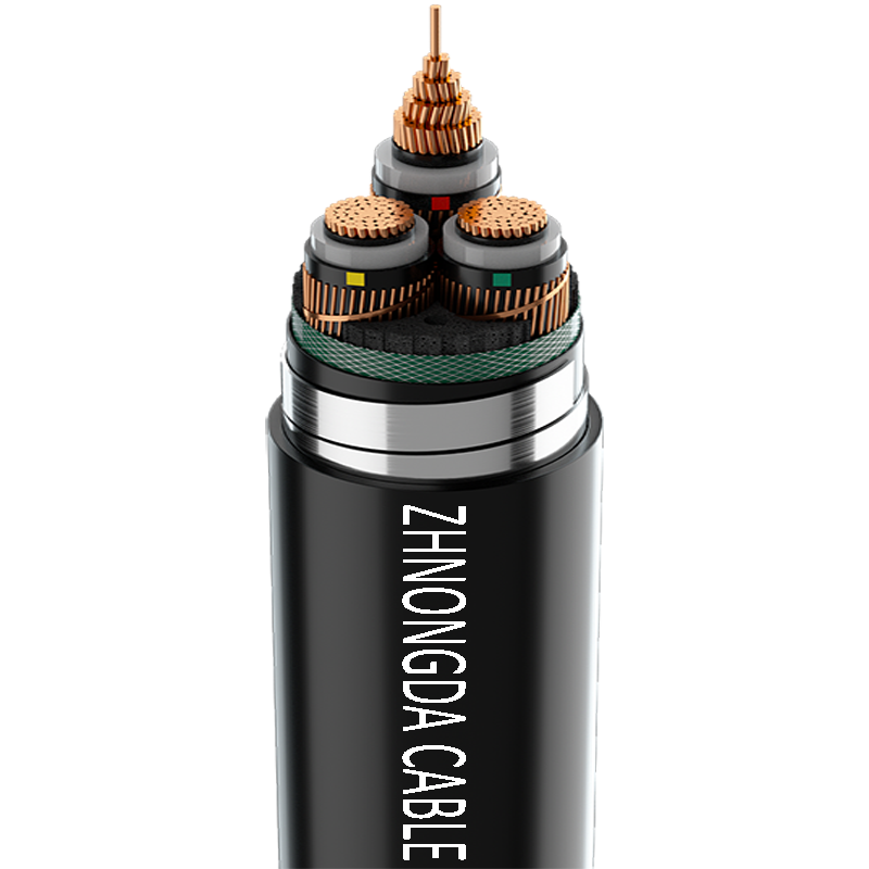
Every industrial cable consists of specific engineered layers. Each layer performs a distinct mechanical or electrical function, working together to maintain system integrity under load.
The conductor carries the electrical current and forms the core of the assembly. Copper and aluminum dominate the market, each offering different conductivity and weight profiles. Stranding configurations heavily influence the physical flexibility and electrical performance of the cable. Solid conductors offer rigidity for permanent, low-vibration installations but are difficult to pull through complex conduit bends. Stranded conductors provide the flexibility needed for standard industrial routing.
In alternating current (AC) systems, engineers must account for the skin effect. Alternating current tends to flow near the surface of the conductor rather than uniformly through its cross-section. Larger stranded conductors, particularly those using segmented or Milliken designs in high-voltage applications, help mitigate this effect, reducing AC resistance and improving overall transmission efficiency.
Insulation surrounds the conductor to prevent phase-to-phase and phase-to-ground faults. It keeps the electrical energy confined to the intended path. Dielectric strength dictates how much voltage the material can withstand before breaking down and allowing current to arc. Thermal tolerance is equally critical. As conductors carry large currents, they generate significant heat. The insulation must withstand these elevated temperatures continuously without melting or degrading.
Modern industrial applications rely heavily on thermosetting plastics. Cross-linked polyethylene (XLPE) and ethylene propylene rubber (EPR) are the standard choices. These materials undergo a chemical process that links their polymer chains, allowing them to maintain their structural integrity at operating temperatures up to 90°C, and withstand emergency overload temperatures up to 130°C.
Shielding becomes a mandatory requirement in medium and high-voltage applications (typically above 2,000 volts). A complete shield system includes a conductor screen and an insulation shield. The conductor screen, usually a semi-conducting polymer layer, smooths out the electrical field around the stranded conductor, preventing localized high-stress points that could initiate partial discharge.
The insulation shield sits over the primary insulation. It consists of a semi-conducting layer followed by a metallic shield (such as copper tape or concentric neutral wires). This metallic layer confines the dielectric field within the cable, equalizes electrical stress across the insulation, and provides a low-impedance path for fault currents to return to the source, ensuring protective relays operate correctly.
The outer layers provide mechanical and environmental protection. Armor protects the internal components from physical crush damage, impact, and rodent attacks. Common armor types include Steel Wire Armor (SWA) for direct burial, Aluminum Wire Armor (AWA) for single-core cables to prevent magnetic heating, and Steel Tape Armor (STA).
The outer jacket seals the entire assembly against the environment. It prevents moisture ingress, resists chemical exposure, and blocks ultraviolet (UV) radiation in outdoor installations. Jacket materials vary widely based on the application, ranging from standard PVC to Low Smoke Zero Halogen (LSZH) compounds required in confined spaces to protect personnel during a fire.
Proper specification requires categorizing the project by voltage class. The engineering requirements shift dramatically as system voltage increases.
We must distinguish heavy-duty, multi-layered cables designed for permanent infrastructure from consumer-grade power cords. Industrial cables are engineered for high capacity, continuous operation, and harsh environments. Conversely, power cords—such as ungrounded, non-polarized two-prong cords used for external devices and A/V equipment—are flexible, temporary connectors. This evaluation focuses strictly on permanent infrastructure components.
Low voltage cables handle up to 1,000 volts and form the bulk of facility wiring.
Medium voltage systems distribute power over longer distances within large facilities or utility networks.
High voltage cables serve as the backbone of regional electrical grids.
| Voltage Class | Voltage Range | Primary Application | Key Engineering Focus |
|---|---|---|---|
| Low Voltage (LV) | Up to 1kV | Secondary distribution, machinery | Ampacity, fire rating, flexibility |
| Medium Voltage (MV) | 1kV to 35kV | Primary distribution, renewables | Shielding, stress control, fault withstand |
| High Voltage (HV) | Above 35kV | Transmission grids, submarine | Dielectric purity, custom FAT, thermal monitoring |
Selecting the optimal Power Cable requires a systematic evaluation of electrical parameters and environmental constraints.
Ampacity defines the maximum continuous current a conductor can carry without exceeding its insulation temperature rating. You cannot simply look at a chart and pick a size based on the load. You must calculate the effective ampacity based on specific installation conditions.
As current travels through a conductor, the inherent resistance of the metal causes a drop in voltage. Over long distances, this drop becomes significant. End-of-line equipment, particularly induction motors, requires a specific voltage range to operate correctly. If the voltage drops too low, motors draw more current, overheat, and fail prematurely.
Engineers must calculate the expected voltage drop for any long run. Industry standards generally recommend a maximum voltage drop of 3% for branch circuits and 5% for feeders. If the calculated drop exceeds these limits, you must increase the conductor cross-sectional area to reduce resistance, even if the smaller wire meets the ampacity requirements.
The physical environment dictates the mechanical protection required for the cable assembly.
Adherence to industry standards is mandatory for safety and legal compliance. You must evaluate cables against specific regional and international codes. For example, medium voltage cables in North America typically must comply with UL 1072 or ICEA standards, while international projects rely on IEC 60502. Utilizing certified products ensures baseline safety, facilitates smooth electrical inspections, and is usually a strict requirement for securing project insurance.
The materials chosen for conductors and insulation directly impact the physical size, weight, and performance of the installation.
The decision between copper and aluminum fundamentally alters the design of the electrical system.
The insulation compound determines the thermal limits and environmental resilience of the circuit.
| Insulation Material | Flexibility | Moisture Resistance | Primary Voltage Use |
|---|---|---|---|
| XLPE | Moderate | Excellent | MV / HV |
| EPR | High | Good | MV / HV Industrial |
| PVC | High | Moderate | LV Only |
Even the most perfectly specified cable will fail if installation risks are ignored. Field execution must match the engineering design.
Routing multiple loaded cables through a single trench or conduit bank creates a massive heat sink. If engineers fail to apply proper grouping derating factors, the cables will exceed their thermal limits, melting the insulation and causing a phase-to-phase fault. Mitigation requires strict adherence to NEC or IEC derating tables during the design phase, ensuring adequate spacing between circuits or increasing conductor sizes to lower operating temperatures.
Every cable has a manufacturer-specified minimum bend radius. Bending a cable too sharply during installation crushes the insulation, deforms the metallic shield, and creates immediate weak points in the dielectric layer. In medium voltage cables, this often leads to partial discharge and eventual blowout. Mitigation involves planning conduit runs with sweeping bends, utilizing proper pulling sheaves, and enforcing rigorous field supervision to prevent contractors from forcing cables around tight corners.
The vast majority of medium and high-voltage cable failures occur at splices and terminations. When the factory-extruded shielding is stripped back to make a connection, the electrical field concentrates heavily at the cutback point. If not properly managed, this stress will destroy the insulation. Mitigation requires the use of engineered termination kits that include stress cones or high-permittivity stress control tubes to distribute the electrical field. Furthermore, only certified, highly trained cable jointers should perform medium and high-voltage splicing.
To ensure a reliable and safe electrical infrastructure, follow these actionable steps when specifying and procuring materials:
A: Power cables are permanent, multi-layered assemblies engineered for infrastructure and high-capacity transmission in industrial settings. Power cords are typically temporary, flexible connectors—often ungrounded or two-prong—used to connect external consumer devices to a standard power source.
A: Determine the correct size by calculating the required ampacity based on the connected load. Factor in the insulation temperature rating, ambient temperature, and installation method. You must also calculate voltage drop for long runs to ensure adequate voltage reaches the equipment.
A: Shielding equalizes electrical stress across the insulation layer. Without it, localized high voltage stress causes partial discharge, which degrades the insulation and leads to premature cable failure. Shielding also provides a safe return path for fault currents.
A: Yes, but only if they are specifically rated for direct burial. These cables must have robust, moisture-resistant outer jackets and often incorporate steel armor to protect against soil pressure, shifting rocks, and rodent damage.
A: The temperature rating indicates the maximum continuous operating temperature the insulation can withstand without degrading. Common ratings are 90°C and 105°C. Operating above this temperature reduces the cable's lifespan and increases the risk of thermal failure.
A: Conduit installations require cables with high pull-tension strength and abrasion-resistant jackets to survive the pulling process. Cable tray installations require cables with specific fire-retardant properties to prevent flame spread across open trays, and they must be rated for tray use.
 简体中文
简体中文 

