

Views: 0 Author: Site Editor Publish Time: 2026-08-12 Origin: Site


A Power Cable functions as the foundational lifeline for industrial operations, data centers, and commercial infrastructure. When these systems fail, facilities face costly downtime and severe safety hazards. At its core, an electrical cable is an assembly of one or more electrical conductors. These conductors often feature specific plugs or couplers to connect equipment directly to a power supply or utility grid. Specifying the correct cable remains a complex engineering challenge. Under-specifying leads to thermal overload, dangerous voltage drops, and compliance failures. Conversely, over-specifying results in unnecessary capital expenditure and routing difficulties during installation. Facility managers and engineers must align specific applications with precise construction materials, voltage ratings, and environmental constraints. This strict alignment ensures long-term operational reliability and maintains strict regulatory compliance across all electrical infrastructure projects.
Conductors form the core of any electrical transmission system. Copper and aluminum dominate the market, each offering distinct advantages. Copper provides superior electrical conductivity. It requires less cross-sectional area to carry the same current as aluminum. This makes copper highly flexible and ideal for tight spaces. You will often specify copper for complex machinery wiring, motor leads, and commercial buildings where conduit space is limited. Copper also resists oxidation better than aluminum, which simplifies termination procedures and reduces the risk of high-resistance connections over time.
Aluminum weighs significantly less than copper. This lighter weight makes aluminum the standard choice for large-scale distribution, feeder circuits, and overhead transmission lines. While aluminum requires a larger diameter to match copper's ampacity, its reduced weight lowers structural support requirements for cable trays and utility poles. When terminating aluminum, installers must use specific oxide-inhibiting compounds and dual-rated lugs to prevent galvanic corrosion and thermal expansion issues. Understanding these mechanical differences is a fundamental part of power cable construction.
| Feature | Copper Conductors | Aluminum Conductors |
|---|---|---|
| Conductivity | Excellent (Standard benchmark) | Good (Requires larger gauge for same ampacity) |
| Weight | Heavy | Lightweight (Approx. 30% of copper) |
| Flexibility | High (Ideal for tight routing and conduit) | Moderate (Prone to fatigue if over-bent) |
| Termination | Standard lugs, minimal oxidation issues | Requires oxide inhibitors and specific torque |
| Primary Use | Commercial, Industrial, Machinery, Branch circuits | Utility grids, Overhead lines, Large feeders |
Insulation surrounds the conductor to prevent phase-to-phase faults and thermal breakdown. Polyvinyl Chloride (PVC) serves well for low-voltage applications. It offers good moisture resistance and flexibility. However, PVC has lower thermal limits, typically rated for 75°C or 90°C, making it unsuitable for high-temperature industrial environments. Cross-linked Polyethylene (XLPE) dominates medium and high-voltage applications. XLPE handles higher operating temperatures (up to 90°C continuous, 130°C emergency overload) and resists moisture exceptionally well. The cross-linking process changes the molecular structure of the polyethylene, preventing it from melting at high temperatures.
Ethylene Propylene Rubber (EPR) provides maximum flexibility. EPR excels in environments requiring tight bending radii and high dielectric strength. It is highly resistant to corona discharge and tracking, making it a favorite for medium-voltage utility substations and industrial plants. Selecting the correct insulation directly impacts the thermal rating, ampacity, and lifespan of the installation. If you install a PVC-insulated cable in a high-ambient temperature area like a boiler room, the insulation will degrade rapidly, leading to a catastrophic ground fault.
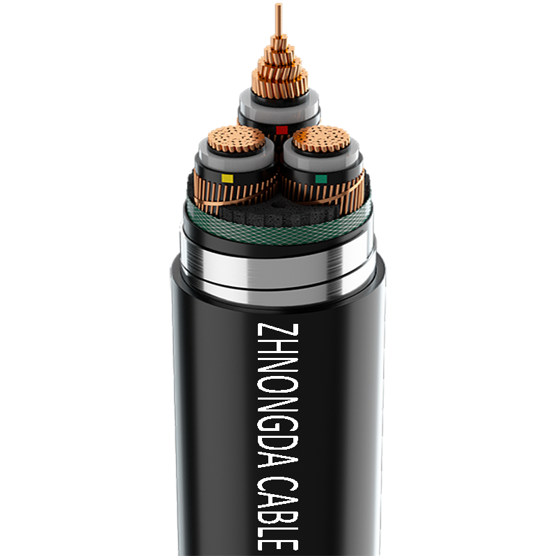
Medium and high-voltage cables require robust shielding mechanisms. Shielding confines the dielectric field within the insulation. This prevents electrical discharges that degrade cable materials over time. Without shielding, the electric field would concentrate at air gaps between the insulation and the jacket, causing corona discharge and ozone generation, which destroys the insulation. Metallic shields, often made of copper tape or concentric copper wires, provide a path for fault currents to return to the source, tripping the protective breaker.
Semi-conductive shielding smooths out the electrical field around the conductor. Extruded semi-conducting layers are applied directly over the conductor and over the insulation. This combination protects sensitive equipment against electromagnetic interference (EMI) and ensures uniform voltage stress distribution. Proper grounding of these shields at termination points and splices ensures safety and system stability during power surges. Failure to properly ground a shielded cable can result in lethal induced voltages on the outer jacket.
The outer sheath protects internal components from external threats. Jacketing materials must resist chemicals, UV radiation, and physical abrasion. Polyvinyl Chloride (PVC) is common for general-purpose jackets, but it releases toxic black smoke when burned. Low Smoke Zero Halogen (LSZH) jackets are mandatory for confined spaces, transit tunnels, and poorly ventilated areas. They prevent the release of toxic halogen gases and thick smoke during a fire, allowing personnel to evacuate safely. Polyurethane (PUR) jackets offer extreme abrasion and oil resistance for rugged environments like mining or robotics.
Armored cables feature interlocked or continuously welded metal layers. Steel Wire Armor (SWA) or Aluminum Wire Armor (AWA) provides massive mechanical protection. You must specify armored designs for direct burial, hazardous locations, or harsh industrial environments where mechanical impact from forklifts or falling debris is a constant threat. Continuously Welded Corrugated Aluminum (MC-HL) armor provides a gas-tight and moisture-tight seal, essential for petrochemical refineries and offshore oil rigs.
Termination points dictate how cables interface with equipment. These include male ends, known as plugs, and female ends, called receptacles or couplers. Standard terminology ensures you match cables to specific appliances accurately. The IEC 60320 standards dictate coupler configurations like C13 and C14, or higher-capacity C19 and C20 connectors. IT equipment and data center hardware rely heavily on these standardized connectors to ensure compatibility across different server manufacturers.
Industrial environments use pin-and-sleeve connectors (IEC 60309) for heavy machinery. These connectors provide watertight seals and mechanical locking mechanisms to prevent accidental disconnection under load. Secure terminations prevent arcing, reduce contact resistance, and maintain the integrity of the entire electrical circuit. A loose connection generates immense heat, which can melt the connector housing and start a fire, regardless of how well the cable itself is constructed.
Heavy-duty cables drive modern manufacturing. These facilities require robust wiring for powering massive motors, compressors, and variable frequency drives (VFDs). Industrial environments expose wiring to harsh conditions. Cables must resist cutting oils, industrial solvents, and continuous mechanical stress from moving drag chains. VFD cables require specialized symmetrical shielding to handle high-frequency noise, common-mode currents, and severe voltage spikes generated by the drive's pulse-width modulation.
Tray cables (TC-ER) are heavily utilized in manufacturing plants. They are rated for installation in cable trays and can be routed exposed between the tray and the equipment if they meet crush and impact requirements. Selecting cables with ruggedized thermoset jackets ensures continuous operation and prevents catastrophic machinery failures that halt production lines. Proper specification of power cable applications in these settings requires a deep understanding of the chemical and mechanical hazards present on the factory floor.
Data centers demand absolute reliability and massive power density. Wiring connects server racks, Uninterruptible Power Supplies (UPS), and Power Distribution Units (PDUs). Utilizing the shortest possible cable lengths improves Power Usage Effectiveness (PUE). Short runs minimize transmission power loss and reduce the heat generated under raised floors or in overhead trays. This optimization lowers the overall cooling requirements of the facility.
High-density server environments also require flexible cables to maintain proper airflow within racks. Bulky, stiff cables block exhaust fans and cause servers to overheat. Data centers frequently utilize specialized whip cables with exact lengths and factory-tested terminations to ensure zero downtime. The focus is always on maximizing efficiency, reducing voltage drop, and maintaining a clean, organized routing system that allows for rapid hardware upgrades.
Utility networks rely on medium and high-voltage infrastructure. These networks connect step-up transformers, substations, and underground city grids. Long-term reliability is paramount for utility providers, as replacing underground lines is highly disruptive. Underground distribution requires cables with superior moisture resistance, often utilizing water-blocking tapes or swellable powders that prevent longitudinal water ingress if the jacket is breached.
Overhead lines demand lightweight, weather-resistant materials. Utilities use Aluminum Conductor Steel Reinforced (ACSR) cables to span long distances between towers. The steel core provides the necessary tensile strength to withstand wind and ice loads, while the outer aluminum strands carry the current. Environmental resilience ensures uninterrupted power delivery across vast geographic areas, from freezing mountain passes to scorching desert solar farms.
Commercial real estate depends on extensive electrical networks. These systems power HVAC units, elevator motors, and emergency egress lighting. Standard office spaces require flexible routing through drop ceilings and raised floors. Metal-Clad (MC) cable is the standard for commercial branch wiring, providing built-in mechanical protection without the labor-intensive process of pulling wire through rigid conduit.
Residential wiring connects household appliances, lighting circuits, and consumer electronics to utility sources. Non-Metallic sheathed cable (NM-B), commonly known as Romex, is the standard for dry, indoor residential applications. Confined or highly populated commercial spaces necessitate Low Smoke Zero Halogen (LSZH) jackets. LSZH materials protect occupants by minimizing toxic smoke emissions during emergencies, ensuring clear visibility for evacuation routes.
Matching the voltage class to your system architecture is the first step. Low-voltage (up to 1000V), medium-voltage (1kV to 35kV), and high-voltage (above 35kV) systems require vastly different cable designs. You must calculate the required ampacity accurately using National Electrical Code (NEC) tables or IEEE standards. Ampacity depends on the continuous load, the conductor material, and the ambient temperature of the installation environment.
Conductor grouping also severely affects ampacity. When you bundle multiple cables in a conduit or cable tray, heat dissipation decreases. You must apply strict derating factors to prevent overheating. For example, if you place more than three current-carrying conductors in a single raceway, you must reduce the allowable ampacity. An undersized electrical power cable will overheat, leading to accelerated insulation aging, short circuits, and potential electrical fires.
Installation environments dictate material selection. Direct burial requires heavy-duty moisture barriers, fungus resistance, and mechanical armor to protect against shifting soil and rocks. Cable trays need flexible, flame-retardant jackets that pass vertical tray flame tests (like IEEE 1202). Conduit installations demand smooth outer sheaths, often with factory-applied slick coatings, to reduce pulling tension and prevent jacket tearing during installation.
Aerial installations require UV-resistant materials and high tensile strength to withstand wind loading. You must evaluate the minimum bend radius for tight routing. Forcing a cable past its minimum bend radius causes micro-cracks in the insulation and damages the metallic shield. Temperature extremes dictate specific jacket types. Cold environments require materials that remain flexible without cracking at -40°C, while high-heat areas near furnaces require silicone or Teflon-based insulation.
Regulatory compliance ensures safety and operational legality. You must evaluate products against NEC/NFPA 70 guidelines for North American installations. UL listings (such as UL 44 for thermoset insulated wires or UL 83 for thermoplastic) verify product safety through rigorous independent testing. CE markings are required for European installations. IEEE standards dictate performance in specific utility and industrial applications.
Sustainability standards like RoHS (Restriction of Hazardous Substances) and REACH restrict heavy metals and dangerous chemicals in cable materials. Specifying non-compliant cables introduces severe liability. If an unlisted cable causes a fire, non-compliance voids facility insurance policies and creates massive operational risks. Always demand factory test reports and certificates of compliance before accepting a cable delivery on site.
Excessive voltage drop degrades equipment performance and shortens lifespan. When voltage drops below the equipment's rated tolerance, motors draw more current to maintain power output. This causes the motor windings to run hotter, eventually burning out the insulation. Sensitive electronics and lighting systems will malfunction or fail to start. You must implement strict mitigation strategies during the design phase.
Up-sizing conductors reduces electrical resistance and minimizes voltage drop over long distances. Shortening cable runs by optimizing the placement of electrical panels and transformers minimizes transmission losses. Always calculate voltage drop before finalizing installation plans. Industry standards typically recommend a maximum voltage drop of 3% for branch circuits and 5% for the total feeder and branch circuit combined. Maintaining these limits ensures efficient power delivery and protects end-use equipment.
Exceeding temperature ratings destroys cable insulation. Harmonic currents, generated by non-linear loads like LED lighting and VFDs, generate excess heat in neutral conductors. Poor ventilation in overloaded cable trays traps heat, accelerating degradation. Thermal breakdown causes insulation to melt, deform, or become brittle. This leads directly to phase-to-phase or phase-to-ground short circuits.
You must recommend continuous thermal monitoring for critical infrastructure. Infrared thermography inspections of terminations and splices can identify hot spots before they fail. Adherence to strict derating calculations prevents thermal overload from the start. Proper spacing in cable trays, maintaining a single layer of cables where possible, ensures adequate airflow for natural convective heat dissipation.
Installation failures compromise the entire system, regardless of cable quality. Exceeding maximum pulling tension stretches copper conductors, reducing their cross-sectional area and increasing resistance. High pulling tension also damages the insulation and jacket. Violating the minimum bend radius causes immediate mechanical damage to the dielectric material and shielding tapes. Improper splicing and termination introduce high-resistance connection points.
These high-resistance points generate intense localized heat and cause electrical fires. You must enforce strict quality assurance protocols during installation. Use proper pulling lubricants to reduce friction in conduits. Utilize dynamometers to monitor pulling tension in real-time. Ensure technicians follow exact manufacturer guidelines for stripping dimensions, crimp tooling, and torque specifications for all terminations.
An electrical cable is a highly engineered component, not a simple commodity. Its construction must align perfectly with its intended application and operating environment. Defining the electrical load and voltage establishes the baseline requirements. Assessing environmental and mechanical threats dictates the necessary armor and jacketing. Selecting appropriate construction materials and connectors ensures long-term reliability. Verifying regulatory compliance protects against liability and safety hazards.
A: While often used interchangeably, a "power cord" typically refers to a flexible cable with pre-installed connectors (a plug and a receptacle) used to connect appliances or IT equipment to a wall outlet. A "power cable" is a broader term that includes heavy-duty, permanent wiring for industrial or utility transmission.
A: The difference lies in their primary function. Power cables transmit high energy to operate machinery and equipment. Control cables transmit low-voltage electrical signals to regulate processes, monitor systems, and control automated machinery.
A: Conductor size, material, and the thermal rating of the insulation dictate ampacity. Larger copper conductors carry more current than smaller aluminum ones. High-temperature insulation allows the cable to safely carry more current without degrading the dielectric material.
A: Common connections link UPS systems, PDUs, and server racks. These environments emphasize high efficiency and require short cable lengths to minimize power loss, reduce heat generation, and improve overall Power Usage Effectiveness (PUE).
A: XLPE offers superior thermal resistance and handles higher operating temperatures than standard PVC. This allows for a higher current carrying capacity. XLPE also provides better moisture resistance and dielectric strength, making it ideal for medium voltage applications.
A: You calculate voltage drop using a formula involving the total current, cable length, and conductor impedance. It is critical to keep this voltage drop below standard industry thresholds, typically 3% for branch circuits or 5% for overall feeders, to ensure equipment operates correctly.
A: Operating beyond the temperature rating causes thermal breakdown. The insulation melts, degrades, or becomes brittle. This catastrophic failure leads to short circuits, severe equipment damage, and significant fire hazards within the facility.
 简体中文
简体中文 

