

Views: 0 Author: Site Editor Publish Time: 2026-08-23 Origin: Site


The increasing electrification of commercial marine vessels, workboats, offshore platforms, and shipboard pump stations relies heavily on Variable Frequency Drives (VFDs) to optimize industrial-grade AC motor efficiency. Modern maritime operations demand precise motor control to reduce fuel consumption and mechanical wear. You will find VFDs running everything from main propulsion thrusters to heavy-duty deck winches. However, integrating these drives introduces complex electrical challenges that standard wiring simply cannot handle.
VFDs generate severe electrical anomalies. These include high-frequency noise, massive voltage spikes, and stray currents. Utilizing standard shipboard power cables for VFD applications leads to premature motor bearing failure, communication network interference, and catastrophic downtime at sea. When a cooling pump fails in open waters due to improper cabling, the operational and safety consequences are severe.
Procurement teams often question if specialized VFD cables are an unnecessary expense. Standard cables compromise both safety and efficiency. We define the Marine VFD Cable as a highly specialized, engineered motor supply solution designed to achieve total electromagnetic compatibility (EMC) and withstand extreme electrical and environmental stressors. Understanding the framework for evaluating, specifying, and installing these cables ensures reliable motor operation.
The foundation of a reliable marine electrical installation begins with the conductor material. Marine environments expose equipment to constant moisture, salt spray, and corrosive atmospheres. Tinned copper conductors are an absolute requirement to prevent oxidation and corrosion. Bare copper degrades rapidly when exposed to saltwater environments, leading to increased resistance and potential fire hazards. Furthermore, the physical routing of cables through complex shipboard architectures demands high flexibility. You must pull these heavy cables through narrow bulkheads, tight cable trays, and complex engine room layouts. Specific stranding classes, such as Class 5 flexible stranding, ensure the cable can navigate tight bending radii without compromising the structural integrity of the individual copper strands. Stiff, lower-class stranding will fight you during installation and put undue stress on termination points.
Standard PVC insulation fails rapidly under the severe electrical stress generated by VFDs. The rapid switching of the drive creates high-voltage spikes that easily exceed the dielectric limits of standard PVC. This leads to insulation breakdown, carbon tracking, and eventual short circuits. Cross-linked polyethylene (XLPE) insulation provides superior dielectric strength, exceptional thermal stability, and high resistance to corona discharge. XLPE maintains its insulating properties even when subjected to the intense thermal cycling and voltage irregularities characteristic of heavy-duty marine motor applications. This robust insulation prevents the capacitive coupling that often leads to system inefficiencies and dangerous leakage currents.
| Insulation Property | Standard PVC | XLPE (Cross-Linked Polyethylene) |
|---|---|---|
| Dielectric Strength | Moderate (Prone to puncture under spikes) | Excellent (Handles high-voltage reflected waves) |
| Thermal Rating | Typically 70°C to 90°C | Up to 90°C continuous, 250°C short circuit |
| Capacitance | High (Increases leakage current) | Low (Reduces capacitive coupling) |
| Moisture Resistance | Good | Superior (Ideal for wet marine environments) |
Effective containment of electromagnetic interference requires a sophisticated shielding architecture. Standard unshielded cables allow high-frequency noise to radiate freely. This noise disrupts nearby sensitive equipment, including dynamic positioning systems and VHF radios. Marine VFD cables utilize various shielding methods. These include heavy copper foil shields, dense tinned copper braided shields, or combination shields that utilize both foil and braid. The necessity of 100% shield coverage cannot be overstated. It is the only way to achieve true electromagnetic compatibility (EMC) in dense marine environments where power and communication lines often run in close proximity. The shield acts as a Faraday cage. It traps the high-frequency noise and directs it safely to ground.
Grounding design is a critical differentiator between standard power cables and specialized VFD solutions. Standard single-ground (asymmetrical) designs force induced currents to find uneven paths back to the source. These currents often travel through the motor chassis and bearings. Three-ground symmetrical constructions distribute the ground wires evenly among the phase conductors. This symmetrical geometry naturally cancels out induced common-mode currents. By neutralizing these stray currents, symmetrical grounding protects high-power shipboard motors from destructive electrical fluting. This significantly extends the operational lifespan of the motor bearings and prevents unexpected mechanical failures.
A common misconception in maritime engineering is that standard marine cables are sufficient for motor drives. Some view specialized VFD cables as an unnecessary luxury. This perspective ignores the operational reality of modern drive technology. The unique electrical characteristics of VFD systems make specialized cables essential for safe, efficient operation. Relying on standard cabling introduces severe vulnerabilities. You turn a minor cost-saving measure into a massive liability when critical propulsion or pumping systems fail unexpectedly at sea. The cost of replacing a destroyed thruster motor far exceeds the initial investment in proper cabling.
Modern VFDs utilize fast-switching insulated-gate bipolar transistors (IGBTs) to control motor speed with high precision. This rapid switching creates high-frequency noise. When standard, unshielded cable connects the drive to the motor, it effectively acts as a giant antenna. It broadcasts severe electromagnetic and radio frequency interference (EMI/RFI) throughout the vessel. This broadcast noise routinely disrupts shipboard programmable logic controllers (PLCs), dynamic positioning systems, and critical VHF marine radios. You create dangerous navigational hazards and operational blind spots when you fail to contain this interference.
The connection between a VFD and an AC motor creates a transmission line effect. Because of impedance mismatches between the cable and the motor terminals, voltage pulses sent from the drive do not fully absorb into the motor. Instead, they reflect back toward the drive. These reflected waves collide with incoming pulses. They compound to create massive voltage spikes. This phenomenon can easily double the peak voltage. Standard cable insulation is not rated for these extreme spikes. It will quickly suffer from dielectric puncture, leading to catastrophic phase-to-phase or phase-to-ground faults.
VFD operation inherently generates common-mode voltage. This induces high-frequency stray currents within the system. These stray currents constantly seek the path of least resistance back to the ground source. In systems utilizing standard asymmetrical cables, this path frequently goes directly through the motor bearings. As the current arcs across the microscopic gap between the bearing ball and the race, it causes intense localized heating. This continuous arcing leads to pitting, frosting, and electrical fluting of the bearing surfaces. You will eventually see the mechanical failure of critical shipboard pump stations, winches, and thrusters.
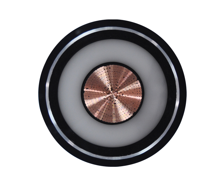
Evaluating cable construction requires a deep understanding of the end-use application. Not all shipboard motors face the same operational demands. Heavy-duty propulsion thrusters require cables with maximum ampacity ratings, symmetrical grounding, and the highest level of mechanical protection against vibration and physical impact. Deck machinery, such as anchor windlasses and cargo cranes, demands exceptional flexibility and resistance to extreme weather conditions and UV exposure. Internal HVAC motor drives may prioritize low smoke zero halogen (LSZH) properties and compact outer diameters to navigate congested interior cable trays safely. You must match the cable construction to the specific environmental and mechanical realities of the installation zone.
The marine environment is notoriously hostile to electrical infrastructure. Outer sheath materials must be evaluated for their resistance to a wide array of harsh conditions. Continuous moisture and salt spray require highly impervious jacket compounds. For vessels operating in the offshore energy sector, the cable jacket must withstand prolonged exposure to harsh chemicals, drilling mud, and synthetic lubricants without swelling or degrading. Cables routed on open decks require robust UV stabilization. Without it, the outer jacket will become brittle and crack under intense sunlight, exposing the internal shielding to corrosive saltwater.
Vessel design inherently limits the available space for electrical routing. Engineers face a constant trade-off between the heavy shielding required for electrical protection and the physical flexibility required to pull cables through tight marine bulkheads and congested cable trays. Selecting a cable with an optimized stranding class and a highly flexible, yet durable, jacket material ensures that installation crews can achieve the necessary bending radii. You must avoid applying excessive pulling tension that could tear the internal shielding or damage the insulation during installation.
Adhering to strict identification standards is vital for safety and maintenance. The correct power cable color code for marine applications ensures that phase conductors and ground wires are instantly recognizable to electrical crews. Following established IEC or IEEE standards for phase identification prevents catastrophic wiring errors. Phase reversal can cause motors to run backward and destroy connected machinery. Consistent color coding streamlines troubleshooting and ensures full compliance during rigorous vessel inspections by port state control authorities. You cannot afford ambiguity when terminating high-voltage motor connections in a cramped engine room.
Proper cable sizing is paramount to prevent overheating and insulation degradation. Engineers must calculate the required ampacity based on the continuous current requirements of the industrial-grade AC motor under maximum load conditions. Crucially, these calculations must factor in severe ambient temperature derating. Engine rooms and mechanical spaces on commercial vessels routinely experience ambient temperatures far exceeding standard industrial environments. Failing to apply the correct derating factors will result in undersized cables that run dangerously hot. This accelerates insulation aging and increases the risk of thermal failure.
| Ambient Temperature (°C) | Ampacity Derating Factor (Typical XLPE 90°C) |
|---|---|
| 30°C | 1.00 |
| 40°C | 0.91 |
| 45°C | 0.87 |
| 50°C | 0.82 |
| 60°C | 0.71 |
Commercial maritime operations are governed by strict international regulations. Utilizing unapproved electrical components invalidates vessel insurance and prevents operational certification. Non-negotiable certifications are required from major classification societies. These include the American Bureau of Shipping (ABS), Det Norske Veritas (DNV), and Lloyd's Register. These approvals guarantee that the cable has undergone rigorous independent testing. They verify its mechanical durability, electrical performance, and suitability for the unforgiving marine environment. You must verify these certificates before authorizing any cable procurement for a commercial vessel.
Marine electrical installations are dictated by specific international standards. IEEE 45 (Recommended Practice for Electrical Installations on Shipboard) and the IEC 60092 series govern every aspect of maritime electrical engineering. These standards dictate the testing parameters for marine VFD cables. They cover everything from conductor resistance and insulation thickness to flame propagation and oil resistance. Compliance with these standards ensures that the cable architecture meets the globally recognized baseline for maritime safety and reliability. Installers must reference these standards when planning cable tray fill ratios and bulkhead penetrations.
Shipboard fires represent one of the most catastrophic hazards at sea. Electrical cables must not contribute to the spread of flames or generate toxic hazards. There is a critical requirement for Low Smoke Zero Halogen (LSZH) and flame-retardant properties. Cables must specifically meet IEC 60332-3 standards for bundled cable fire tests. LSZH jackets ensure that, in the event of a fire, the cables emit minimal visible smoke. This aids crew evacuation. They also release zero corrosive halogen gases, protecting both human life and sensitive electronic equipment from secondary damage.
The most robust shielding architecture is rendered useless if it is compromised at the termination point. A frequent implementation risk involves stripping back the shield too far or failing to ground it properly at the motor terminal box or the drive cabinet. You must use specialized, EMC-rated marine cable glands. These glands provide continuous 360-degree contact with the cable shield. They ensure a low-impedance path to ground and prevent high-frequency noise from leaking out at the connection points. Standard brass glands will not provide the necessary EMC protection.
Large commercial vessels often require long cable runs between the main switchboard and remote deck machinery. These extended lengths exacerbate the physical limitations of VFD cable runs. As cable length increases, the capacitance of the cable increases. This amplifies the amplitude of reflected wave voltage spikes and causes significant voltage drop. Engineers must strictly adhere to maximum cable length guidelines provided by the drive manufacturer. When runs exceed these limits, mitigation strategies are necessary to protect the motor insulation.
Physical routing practices heavily influence system reliability. Even with heavily shielded VFD cables, running high-power motor supply lines directly alongside sensitive low-voltage instrumentation cables invites cross-talk and data corruption. Best practices for cable tray routing demand strict physical separation distances. You must maintain a minimum separation distance. Often, this means utilizing grounded metal dividers within the trays or routing power and control cables in entirely separate parallel runs. This is essential to maintain signal integrity for shipboard automation and monitoring networks.
Utilizing standard marine power cable for VFD applications introduces severe operational risks. The extreme electrical stressors generated by modern drives demand specialized solutions. Marine VFD cables are an essential component of modern shipboard electrical systems, engineered specifically to ensure motor efficiency, protect sensitive electronics from interference, and maintain maritime safety.
A: For any modern VFD-driven AC motor, specialized shielding and insulation are absolutely essential. Standard cables cannot handle the high-frequency noise and voltage spikes generated by the drive. Investing in a proper VFD cable prevents rapid equipment failure, bearing damage, and severe electromagnetic interference, making it a necessary operational requirement rather than an overkill expense.
A: The primary differences lie in the internal architecture. Marine VFD cables feature heavy-duty shielding to contain high-frequency noise, robust XLPE insulation to withstand extreme voltage spikes, and specialized grounding configurations designed specifically to neutralize stray currents that damage motor bearings.
A: While smaller motors may operate adequately with asymmetrical grounds, symmetrical designs are highly recommended and often required for larger motors over 50HP. The symmetrical three-ground design naturally cancels out induced common-mode currents, preventing electrical fluting and catastrophic damage to the motor bearings over time.
A: Phase conductors and grounds must be color-coded according to regional marine standards, such as IEC 60092. Adhering to the correct power cable color code ensures safe termination, prevents dangerous phase reversal during installation, and guarantees compliance during routine maintenance and port state control inspections.
A: Maximum length is strictly dictated by the VFD manufacturer's specifications. Extended lengths increase capacitive coupling and amplify reflected voltage spikes. For cable runs exceeding 100 to 150 feet, engineers usually must specify load reactors or dV/dt filters to protect the motor insulation from extreme voltage peaks.
A: XLPE features significantly lower capacitance and much higher dielectric strength compared to standard PVC. This robust thermal and electrical stability prevents the insulation breakdown and short circuits commonly caused by the severe reflected wave voltage spikes inherent in VFD operation.
A: While not all VFD cables are inherently halogen-free, LSZH jackets are typically specified for enclosed shipboard environments. Meeting ABS and DNV safety standards for interior routing requires LSZH materials to ensure that, during a fire, the cables emit minimal smoke and zero toxic, corrosive gases.
 简体中文
简体中文 

