

Views: 0 Author: Site Editor Publish Time: 2026-08-16 Origin: Site


A High Voltage Power Cable serves as the critical artery of modern power transmission infrastructure. Selecting the correct cable directly dictates system reliability, safety, and operational continuity across utility grids, renewable energy installations, and heavy industrial environments. Specification errors carry severe consequences. Catastrophic failures, compliance penalties, safety hazards, and massive downtime disrupt operations when buried or highly integrated high-tension infrastructure fails. Replacing a compromised underground transmission line requires extensive excavation, specialized labor, and extended outage periods.
This guide provides a rigorous, evidence-based framework for evaluating, specifying, and procuring the correct transmission assets. You will learn how to navigate environmental constraints, manage electrical loads, and maximize transmission efficiency without compromising safety. By understanding the core material science, shielding architectures, and installation risks, engineering teams can build resilient power networks that withstand extreme operational demands and harsh environmental conditions.
Electrical cables are categorized strictly by their voltage ratings. Standard industry benchmarks classify a medium voltage cable between 1kV and 35kV. A true high voltage cable operates above 35kV, frequently reaching up to 230kV. Anything exceeding 230kV falls into the extra-high voltage (EHV) or ultra-high voltage (UHV) categories. In engineering schematics and utility planning, these are frequently referred to as high-tension (HT) cables. Correct classification ensures you apply the right safety margins, insulation thicknesses, and testing protocols during infrastructure development.
| Voltage Class | Voltage Range | Typical Application | Insulation Requirement |
|---|---|---|---|
| Low Voltage (LV) | Up to 1kV | Residential, commercial wiring, secondary distribution | Basic extruded polymer (PVC, XLPE) |
| Medium Voltage (MV) | 1kV to 35kV | Primary distribution, industrial plant networks | XLPE/EPR with semi-conductive screens |
| High Voltage (HV) | 35kV to 230kV | Sub-transmission, grid interconnects, offshore wind | Thick XLPE, metallic shielding, water barriers |
| Extra-High Voltage (EHV) | Above 230kV | Long-haul national grid transmission | Advanced XLPE, complex metallic sheathing |
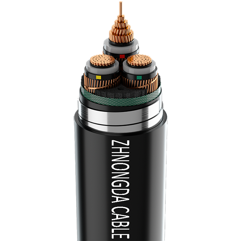
The structural anatomy differs drastically across voltage classes. A low voltage power cable generally operates under 1kV. It relies on basic insulation layers for localized distribution in commercial buildings or residential wiring. In contrast, high voltage variants require complex semi-conductive layers and heavy metallic shields. These internal structures manage intense electrical stress and prevent the dielectric breakdown of the insulation. High voltage lines connect power plants to primary grid transmission networks, demanding robust protection against extreme environmental and electrical loads. The absence of a metallic shield in low voltage designs makes them entirely unsuitable for handling the intense electrical fields generated above 35kV.
Modern grid infrastructure relies on two distinct transmission architectures. High Voltage Alternating Current (HVAC) cables dominate traditional, shorter-distance AC grid networks and substations. They integrate seamlessly with existing transformer infrastructure and are the standard for municipal sub-transmission. High Voltage Direct Current (HVDC) cables serve a different purpose. They are necessary for ultra-long-distance transmission, offshore wind farm interconnects, and asynchronous grid connections. HVDC technology features lower capacitance and significantly reduced transmission losses over hundreds of kilometers.
Conductor material dictates the physical and electrical characteristics of the transmission line. Copper offers superior conductivity and high tensile strength. It is ideal for space-constrained areas where a smaller cable diameter is mandatory, such as congested underground urban duct banks. Aluminum provides significant weight reduction and substantial material savings for long-distance runs. Advanced conductor designs, such as Milliken or segmental conductors, mitigate the skin effect and reduce AC resistance in large cross-section cables. Segmental construction divides the conductor into insulated pie-shaped sections, forcing the current to distribute more evenly across the entire cross-sectional area.
| Conductor Material | Conductivity | Weight | Primary Use Case |
|---|---|---|---|
| Copper (Cu) | 100% (IACS reference) | Heavy | Space-constrained urban ducts, high-load industrial |
| Aluminum (Al) | ~61% of Copper | Lightweight | Long-distance utility transmission, overhead lines |
Insulation integrity determines the lifespan of the transmission network. Cross-Linked Polyethylene (XLPE) dominates modern applications. It delivers a high thermal rating, low dielectric losses, and excellent performance in HVDC environments. XLPE can withstand continuous operating temperatures of 90°C and short-circuit temperatures up to 250°C. Ethylene Propylene Rubber (EPR) offers an alternative for environments requiring higher flexibility. EPR provides superior resistance to electrical treeing, though it generally exhibits higher dielectric losses than XLPE. The industry has largely abandoned paper-insulated lead-covered (PILC) cables, favoring the reliability, easier splicing, and lower maintenance requirements of extruded polymeric dielectrics.
Managing electrical fields requires precise shielding. Semi-conductive screens surround the conductor and the insulation. They equalize electrical stress, prevent corona discharge, and avoid localized insulation breakdown by ensuring a perfectly smooth interface between the conductor and the dielectric material. Mechanical protection is equally vital. Steel wire armor (SWA) or corrugated aluminum sheaths defend against physical impact, rodent damage, and heavy crush loads during direct burial. The metallic shield also provides a critical fault current return path, ensuring that breaker systems trip immediately in the event of a ground fault.
Routing environments dictate the physical construction of the cable. Underground burial requires assessing soil thermal resistivity, moisture ingress risks, and duct bank design. Poor thermal backfill can cause the cable to overheat and fail prematurely. Submarine applications demand specialized engineering to withstand hydrostatic pressure, longitudinal water tightness, and dynamic mechanical stress from ocean currents. Submarine cables often incorporate heavy galvanized steel wire armor and extruded lead sheaths to guarantee absolute water impermeability. Overhead or exposed routing introduces different challenges. Cables in these environments must resist intense UV radiation, extreme temperature fluctuations, and heavy wind or ice loading.
Ampacity requirements must align with continuous load profiles and emergency overload conditions. Engineers calculate these ratings based on the maximum permissible operating temperature of the insulation and the thermal dissipation capabilities of the surrounding environment. Short-circuit current ratings also influence the cross-sectional area of the metallic screen. Transmission efficiency requires evaluating dielectric losses and reactive power compensation. High capacitance in long HVAC lines generates reactive power, which limits active power transfer and necessitates expensive compensation stations. This is why HVDC becomes the mandatory choice for transmission lengths exceeding 50 to 80 kilometers underwater.
Procurement must mandate strict adherence to international testing standards. IEC 60840 covers voltages above 30kV up to 150kV. IEC 62067 dictates requirements for extra-high voltage lines above 150kV. Factory acceptance testing (FAT) is non-negotiable. Routine partial discharge tests and high-voltage withstand tests verify that the insulation is free from micro-voids and manufacturing defects before the cable leaves the facility.
Pulling heavy, rigid cables through trenches or ducts introduces severe mechanical stress. Exceeding the manufacturer's minimum bend radius causes invisible micro-fractures in the insulation screen. These fractures concentrate electrical fields and inevitably lead to premature dielectric failure. Installation teams must use motorized rollers, proper pulling tensions, and calculated routing paths to protect the structural integrity of the line. Dynamometers should be used during the pull to ensure tension limits are never exceeded.
Joints and terminations represent the primary failure points in high voltage systems. Splicing disrupts the factory-extruded insulation, creating localized electrical field concentrations. Mitigation requires strict quality control. Utilize certified high-voltage jointers and pre-molded accessories to ensure consistent field grading. Conduct rigorous post-installation site testing to verify splice integrity before energizing the circuit.
Water treeing degrades extruded dielectrics over time. Microscopic moisture droplets penetrate the insulation under the influence of strong electrical fields. These droplets form tree-like structures that eventually bridge the insulation, causing a catastrophic short circuit. Preventative design choices include water-swellable tapes and powders that block longitudinal moisture migration if the outer sheath is breached. Extruded metallic sheaths, typically lead or seamless aluminum, provide an absolute radial moisture barrier for critical underground and submarine lines.
Modern high voltage networks require continuous condition monitoring to ensure lifecycle reliability. Integrating fiber optic cables directly into the metallic shield or armor layer allows for real-time data acquisition. Distributed Temperature Sensing (DTS) utilizes these fibers to monitor the thermal profile of the entire cable route. This allows operators to identify localized hot spots caused by dry soil conditions or external heat sources. Distributed Acoustic Sensing (DAS) detects vibrations, providing early warning of third-party excavation activities near the buried line. By leveraging DTS and DAS, grid operators can dynamically rate the cable, pushing more current during favorable thermal conditions while preventing catastrophic overheating.
Specifying a high voltage power cable is a rigorous exercise in technical risk management. It requires precise alignment between electrical demands, environmental realities, and material science. You must prioritize insulation integrity, appropriate shielding, and strict standard compliance to ensure grid reliability.
A: While voltages above 1kV separate low from medium voltage, true high voltage typically spans the 35kV threshold up to 220kV or 400kV. This distinguishes it from medium voltage distribution and extra-high voltage transmission networks.
A: High voltage lines require semi-conductive screens and heavy metallic shielding to manage intense electrical fields. Low voltage lines rely on simple insulation layers since they do not generate the same level of dielectric stress.
A: HVAC is standard for shorter AC grid distribution and substation connections. HVDC is optimized for ultra-long-distance, low-loss transmission and submarine interconnects where AC capacitance would severely limit power transfer.
A: A properly specified and installed underground cable typically lasts 30 to 40 years. Lifespan depends heavily on soil thermal conditions, load cycling, and the effectiveness of the radial moisture protection.
A: Shielding confines the dielectric field within the insulation layer. It prevents corona discharge, equalizes electrical stress, and provides a safe, controlled path for fault currents to reach the ground.
A: The primary causes include third-party mechanical damage during excavation, poor splicing or termination workmanship, and moisture-induced insulation degradation known as water treeing.
A: Yes, aluminum is standard practice for utility-scale projects due to its lower weight and cost. Engineers must accommodate its lower conductivity by increasing the cross-sectional area of the conductor.
 简体中文
简体中文 

