

Views: 0 Author: Site Editor Publish Time: 2026-08-09 Origin: Site


Unplanned equipment shutdowns, premature motor failures, and localized overheating often trace back to a fundamental but overlooked electrical metric: power loss between the source and the load. Specifying inadequate wiring infrastructure leads to operational inefficiencies, safety hazards, and non-compliance with electrical codes. For facilities managing heavy loads, under-sizing cables to save upfront costs frequently results in exponential long-term maintenance expenses.
Mitigating these risks requires a technical understanding of what causes Power Cable Voltage Drop. By evaluating conductor properties, environmental variables, and installation methods, engineering and procurement teams can specify the correct Industrial Power Cable for their specific operational demands.
Before diagnosing the root cause, facilities must identify the physical symptoms indicating that voltage is being lost between the power source and the load. Field technicians often encounter these issues during routine operations, and recognizing them early prevents catastrophic equipment failure.
Sluggish motor acceleration is a primary indicator. You will notice delays in motor startup times, accompanied by extended periods of high inrush current. The motor may whine excessively and fail to reach optimal RPMs within the expected timeframe. This happens because the motor attempts to draw more current to compensate for the lack of voltage, which in turn generates excessive heat within the motor windings.
Erratic control systems also point to voltage issues. Unexplained resets, undervoltage faults, or erratic readings in PLCs, sensors, and sensitive electronics that share the affected circuit are common. When the voltage dips below the minimum operating threshold of a power supply unit, the logic controller will simply drop out or reboot, causing sudden process interruptions.
Thermal signatures provide physical evidence. Localized hot spots along the cable run or at termination points are often detectable via infrared thermography long before physical insulation melting or burning odors occur. Heat is the direct byproduct of electrical resistance.
| Symptom Category | Observable Field Indicators | Immediate Operational Impact |
|---|---|---|
| Motor Performance | Slow acceleration, excessive whining, high sustained inrush current | Overheating windings, premature bearing wear, tripped breakers |
| Control Systems | PLC reboots, sensor flickering, contactor chatter | Process shutdowns, data loss, erratic automated responses |
| Thermal Output | Hot conduits, glowing terminations under IR scan, melted insulation | Fire hazards, accelerated insulation degradation, short circuits |
| Lighting | Dimming high-bay lights during heavy equipment startup | Poor visibility, indication of shared circuit overload |
Establish the baseline physics of why voltage drop occurs to define what constitutes a successful cable specification. The goal is delivering adequate voltage to the load under peak operational conditions, not just during idle states.
The relationship between Voltage (V), Current (I), and Resistance (R) is defined using Ohm's Law (V = I x R). No conductor is a perfect transmitter of electricity. All materials possess inherent electrical resistance that converts a portion of electrical energy into heat. When current pushes through a conductor, the resistance of the metal opposes the flow. This opposition consumes energy, which manifests as a drop in voltage from the source to the destination.
To calculate the expected drop, engineers follow specific steps:
A common misconception involves static voltage measurement. Voltage drop is only measurable and impactful when current is actively flowing under load. If you measure voltage at the end of a long, disconnected wire, it will read the same as the source. The drop only occurs when the circuit is closed and current flows.
Inrush currents, such as motor startups, create temporary, severe voltage drops that can trigger undervoltage faults if the cable is not sized for peak transient loads. A motor might draw 50 amps while running, but 300 amps for the first two seconds of startup. If the wire is only sized for 50 amps, the resistance during that 300-amp spike will cause the voltage to plummet, potentially stalling the motor.
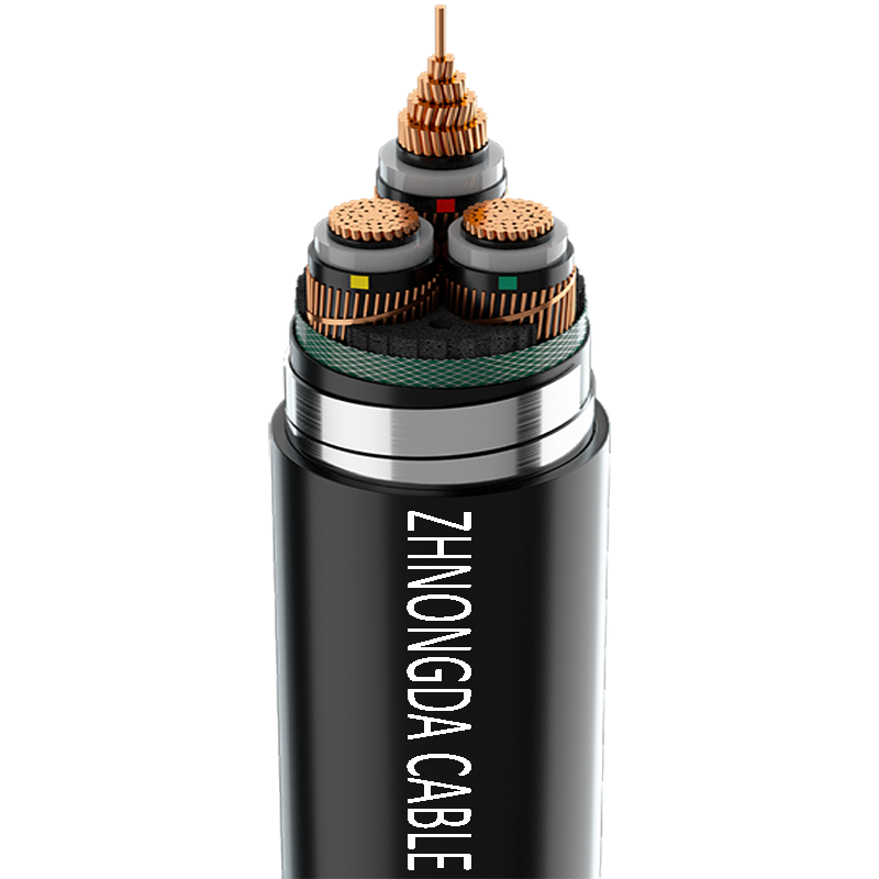
Break down the physical and material specifications that buyers must evaluate when comparing cable options. Selecting the right wire involves balancing physical constraints with electrical requirements.
Resistance increases linearly with cable length. A 200-foot run has twice the resistance of a 100-foot run of the same wire. Conversely, resistance decreases as the cross-sectional area or gauge size increases. A thicker wire provides a wider path for electrons, reducing the bottleneck effect.
When routing long distances, upsizing the conductor is the primary method to keep voltage drop within acceptable limits. If a 100-amp load requires a #2 AWG wire for a 50-foot run, extending that run to 300 feet might require upsizing to a 2/0 AWG wire simply to overcome the resistance added by the extra distance.
Copper has a specific resistivity of approximately 1.68×10^-8 Ω·m, while aluminum is roughly 2.82×10^-8 Ω·m. Copper is a superior conductor, meaning it offers less resistance for a given size. However, aluminum is lighter and highly cost-effective for long, heavy-feeder runs.
Because aluminum has higher resistance, you must use a larger gauge to match the voltage drop performance of copper. This requires larger conduits and different termination lugs, which must be factored into the installation planning.
| Material | Conductivity Rating | Weight Profile | Typical Application |
|---|---|---|---|
| Copper | 100% (Standard) | Heavy | Branch circuits, motor leads, tight conduit spaces |
| Aluminum | Approx. 61% of Copper | Lightweight | Long feeder runs, overhead service drops, large distribution |
In AC circuits, particularly large industrial power cables, alternating magnetic fields create inductive reactance. This is an additional form of opposition to current flow that does not exist in DC circuits.
Skin effect and proximity effect in large AC conductors push current to the outer edges of the wire. The center of the conductor carries very little current. This effectively reduces the usable cross-sectional area of the wire, increasing the overall impedance and worsening the voltage drop. This is why very large single conductors are sometimes replaced with multiple smaller parallel conductors.
Highlight how the physical environment and installation methods alter the performance of an otherwise correctly specified cable. A wire that performs perfectly in a climate-controlled room may fail in a harsh industrial setting.
Metals have a positive temperature coefficient. As ambient temperature rises, conductor resistance increases, exacerbating voltage drop. The hotter the wire gets, the harder it is to push current through it.
Specifying appropriate temperature-rated insulation, such as 90°C versus 105°C, is vital for high-heat environments like foundries or boiler rooms. While the insulation itself does not change the resistance of the copper, a higher rating allows the wire to safely operate at higher temperatures without melting, which is necessary when ambient heat pushes the conductor's operating temperature up.
Routing multiple cables in a single conduit or tightly bundling them restricts airflow and heat dissipation. When wires cannot shed heat, their internal temperature rises, which increases resistance.
NEC ampacity derating factors dictate that bundled cables run hotter, thereby increasing resistance and necessitating larger conductors to prevent excessive voltage drop. If you run nine current-carrying conductors in a single pipe, you must significantly reduce the allowable current for those wires, often forcing an upsize in gauge to maintain safe operating temperatures and acceptable voltage levels.
Address post-installation factors that cause voltage drop and how to mitigate them through proper hardware selection and maintenance protocols. Even the best-designed system will degrade if not maintained.
Physical trauma, such as crushing from heavy machinery or over-tensioning during installation pulling, can sever individual copper or aluminum strands within a stranded industrial power cable.
Broken strands effectively reduce the cable's overall cross-sectional area at the site of the damage. If a 19-strand wire loses 5 strands to a forklift crush, that specific section of wire now has the current-carrying capacity of a much smaller gauge. This creates a high-resistance bottleneck that induces a severe localized voltage drop and generates massive amounts of heat, often leading to insulation failure.
Corrosion and oxidation at termination points introduce localized resistance. When a lug is exposed to moisture or chemical vapors, a resistive layer forms between the wire and the connection point.
Dissimilar metals can accelerate galvanic corrosion, leading to poor connections that mimic or worsen cable-length voltage drops. If an aluminum wire is terminated to a copper busbar without proper anti-oxidant compound and dual-rated lugs, the connection will rapidly degrade. Regular inspection and proper torqueing of connections are essential to maintain low-resistance pathways.
To effectively manage voltage drop, take the following steps:
A: The NEC recommends a maximum combined voltage drop of 5% for feeders and branch circuits. However, sensitive electronics and heavy motors may require stricter internal tolerances, often around 3% or less to ensure reliable operation during peak load conditions.
A: Insulation type does not directly change conductor resistance. However, higher temperature ratings allow the cable to operate safely at elevated temperatures, which influences ampacity calculations and overall circuit design in hot environments.
A: Solutions include replacing the run with a larger gauge cable, shortening the cable length if possible, reducing the load on the circuit, or installing a voltage regulator or transformer closer to the load to boost the voltage locally.
A: Voltage drop is a product of current and resistance (V = I x R). Without current flowing through the circuit, there is no measurable voltage loss across the conductor. The source voltage will be present at the end of the line until a load is applied.
A: Yes. Loose, corroded, or improperly torqued connections create high localized resistance. This leads to significant voltage drops across the connection point and dangerous heat generation, which can eventually cause electrical fires or equipment failure.
 简体中文
简体中文 

