

Views: 0 Author: Site Editor Publish Time: 2026-08-28 Origin: Site


Calculating Power Cable Ampacity is a high-stakes engineering requirement that directly impacts the safety, reliability, and physical integrity of electrical infrastructure. Undersizing conductors leads to catastrophic thermal degradation, insulation failure, and severe fire risks. Conversely, oversizing results in unnecessary copper or aluminum expenditures and creates significant installation difficulties at equipment terminals. A common misconception is that determining cable current rating is as simple as applying the basic electrical formula where current equals power divided by voltage. In reality, establishing the correct cable load capacity is a complex thermal engineering challenge. It requires balancing internal heat generation against external heat dissipation across highly variable installation environments while maintaining strict compliance with national electrical codes. This technical guide breaks down the standardized frameworks established by the NEC and IEC, critical derating factors, the step-by-step mathematical process for accurate power cable sizing, and when to rely on manual calculations versus advanced thermal modeling software.
Ampacity is strictly defined as the maximum continuous current a conductor can carry under specific conditions without exceeding its thermal degradation point. It is a measurement of thermal endurance rather than just electrical throughput. You cannot push current through a wire without generating heat. The physics of a cable's current rating revolves around a constant dynamic between heat generation and heat dissipation.
As electrical current flows through a conductor, electrical resistance generates heat. This is known as I^2R loss, where current squared multiplied by resistance equals the wattage of heat produced. The surrounding environment acts as a thermal resistor. Open air, soil, concrete, and PVC conduit all possess different thermal resistance values. They either trap or dissipate the heat generated by the conductor.
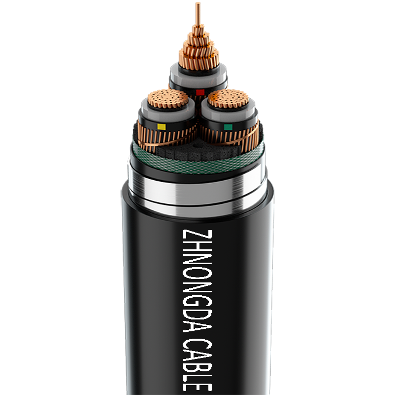
The physical construction of the cable significantly influences this thermal dynamic. Metallic armor, non-metallic sheathing, and internal shielding act as thermal barriers. These layers trap heat within the conductor core. Cross-linked polyethylene (XLPE) insulation handles heat differently than polyvinyl chloride (PVC). The materials dictate the overall thermal limit of the assembly.
Basic electrical formulas fall short because they only calculate the expected load. Dividing wattage by voltage determines how much current the equipment will draw. It does absolutely nothing to determine the physical conductor size required to safely carry that load in a specific physical environment. You must account for the thermal resistance of the entire installation path.
| Installation Medium | Thermal Dissipation Capability | Impact on Ampacity |
|---|---|---|
| Free Air (Cable Tray) | Excellent | Maximum allowable base ampacity |
| Direct Buried (Soil) | Moderate to Poor (Depends on moisture) | Requires calculation of soil thermal resistivity (Rho) |
| Underground Concrete Duct Bank | Poor | Significant derating required due to trapped heat |
| Thermal Insulation (Walls/Attics) | Very Poor | Strict code limitations (e.g., 60°C column limit) |
Electrical engineers rely on foundational codes to establish baseline ampacities. The National Electrical Code (NEC) in North America and the International Electrotechnical Commission (IEC) standards globally provide the legal and technical frameworks for these calculations.
These codes provide standard tables that establish base ampacity. NEC Table 310.16 is the most frequently used chart. It assumes a baseline ambient air temperature of 30°C (86°F) and no more than three current-carrying conductors in a single raceway or cable. NEC Table 310.15(C)(1) provides baselines for cables operating in free air, which naturally allows for higher current ratings due to better cooling.
Conductor material and insulation ratings are critical starting points. Copper offers higher conductivity and lower resistance than aluminum. This allows for smaller copper conductor sizes for the exact same load. Insulation types are categorized by their maximum safe operating temperatures. Higher temperature ratings allow the conductor to carry more current safely before the insulation melts or degrades.
Engineers must always apply the "weakest link" rule. Equipment terminal temperature limits often restrict the usable ampacity to the 75°C column, regardless of whether the wire itself has a 90°C rating. UL 486A-486B standardizes most modern equipment lugs at 75°C. If you push 90°C ampacity through a 75°C lug, the terminal will overheat, loosen, and potentially cause an arc fault. You use the 90°C rating for derating math, but the final allowable current cannot exceed the 75°C terminal limit.
Real-world installation variables force engineers to reduce the base ampacity to ensure safe operation. You rarely install cables in the perfect 30°C environment with only three wires in a pipe. These environmental realities require strict mathematical adjustments.
Ambient temperature correction is mandatory when operating in environments hotter than the 30°C baseline. Locations like boiler rooms, factory ceilings, or rooftop conduits exposed to direct sunlight severely reduce the cable's ability to dissipate heat. If the air around the cable is already hot, the heat from the I^2R losses cannot escape. Engineers must apply a mathematical correction factor from NEC Table 310.15(B)(1) to reduce the allowable ampacity.
Conductor bundling creates a mutual heating effect. When four or more current-carrying conductors are bundled in a single conduit, cable tray, or trench, they bake each other. The heat from one wire raises the ambient temperature for the adjacent wires. The NEC requires adjustment factors to reduce the ampacity based on the number of bundled conductors.
| Number of Current-Carrying Conductors | Percent of Values in Ampacity Tables |
|---|---|
| 4 through 6 | 80% |
| 7 through 9 | 70% |
| 10 through 20 | 50% |
| 21 through 30 | 45% |
Installation conditions drastically alter thermal resistance. Free air allows for rapid heat dissipation. Buried conduits and underground duct banks trap heat in the earth. In underground calculations, engineers must account for soil thermal resistivity (Rho). Dry, sandy soil traps heat, requiring larger cables. Wet, compacted soil conducts heat away from the conduit, allowing for better ampacity.
Calculating the correct conductor size requires a systematic approach. You must follow the math sequentially to ensure safety and code compliance. Skipping steps leads to dangerous undersizing.
For example, assume a 100A continuous load. You need 125A of capacity. You have six THHN copper conductors in a conduit on a roof with a 40°C ambient temperature. A 1/0 AWG copper wire has a 90°C base ampacity of 170A. Multiply 170A by the 40°C correction factor (0.91). That equals 154.7A. Now multiply by the bundling factor for six wires (0.80). The final derated ampacity is 123.76A. This is less than the required 125A. You must upsize to 2/0 AWG.
Professional engineering environments utilize two primary methods for determining ampacity: manual table calculations and automated modeling software. The choice depends entirely on the complexity of the installation.
Manual, step-by-step calculations using NEC or IEC tables are sufficient and legally compliant for standard commercial wiring. Simple industrial motor feeds, indoor panel feeders, and basic branch circuits fit this category. These scenarios involve predictable environments and standard installation methods where the code book provides adequate safety margins.
Manual tables fail in complex scenarios. Specialized cable sizing software is necessary for non-standard duct banks, transient thermal analysis, or varying load profiles. The Neher-McGrath equations used for underground thermal dynamics are too complex for manual daily calculation. Software accounts for complex thermal dynamics that simple tables cannot address.
Advanced software allows engineers to import exact cable geometries and thermal profiles from specific manufacturers. This provides highly precise modeling. You move beyond generic code tables to ensure absolute accuracy in critical infrastructure. Software can model the exact spacing of conduits in a concrete pour and calculate the mutual heating across different circuits.
Software prevents costly oversizing and mitigates the severe risk of thermal failures in high-stakes projects. While it requires specialized training, the material savings from optimizing conductor sizes in a massive industrial facility easily justify the investment.
Frequent engineering and installation errors compromise electrical safety. Field modifications often invalidate the original engineering calculations.
Misapplying NM-B cable specifications is a widespread industry error. Modern NM-B (Romex) cable has 90°C insulation on the internal conductors. However, NEC 334.80 strictly limits its final allowable ampacity to the 60°C column. This ensures safety in residential and light-commercial thermal environments where the cable is buried in fiberglass or cellulose wall insulation.
Ignoring harmonic currents is another critical risk. Non-linear loads, such as variable frequency drives, LED drivers, and server racks, create harmonic distortion. This causes excessive heating in neutral conductors. In a standard 3-phase system, the neutral carries unbalanced load. With high harmonics, the neutral carries significant current and generates heat. It must then be counted as a current-carrying conductor for bundling derating purposes.
Calculation errors lead to significant operational impacts. Under-sizing causes immediate code violations, insulation degradation, and fire risks. Over-sizing wastes capital expenditure on excessive copper. It also complicates termination at equipment lugs, often requiring expensive pin adapters or larger enclosures to accommodate the bending radius of massive cables.
A: Expected load is the current the equipment will draw, calculated by dividing power by voltage. Ampacity is the maximum current the physical cable can safely carry in its specific installation environment without overheating.
A: Base ampacity tables assume ideal conditions, usually 30°C ambient air and no more than three bundled conductors. You must derate the cable if the environment is hotter or if multiple conductors are bundled together, as these factors trap heat.
A: No. Even if the wire is rated for 90°C, the equipment terminals it connects to are typically only rated for 75°C. You must use the 75°C column as your final limit to ensure the terminals do not overheat.
A: Use software for complex installations like underground duct banks, densely packed cable trays, or high-voltage runs where standard tables cannot accurately account for the complex thermal interactions and soil thermal resistivity.
A: Although modern NM-B cable uses 90°C insulation, the NEC restricts its allowable ampacity to the 60°C column to prevent overheating when installed in thermally insulated residential walls and ceilings.
A: Harmonic currents from non-linear loads cause excessive heating in the neutral wire. This requires you to count the neutral as a current-carrying conductor, which often triggers stricter bundling derating factors.
 简体中文
简体中文 

