

Views: 0 Author: Site Editor Publish Time: 2026-08-22 Origin: Site


Modern power grids face a fundamental engineering challenge. They must transmit massive electrical loads across vast distances without incurring crippling energy losses. This analysis focuses strictly on macro-grid transmission infrastructure. We must distinguish this scale from consumer-level high voltage applications, such as 400V to 800V electric vehicle systems or standard residential distribution networks. Standard transmission infrastructure struggles to keep pace with current generation trends. As energy demands scale and renewable generation sites emerge further from urban load centers, grid planners face escalating problems. They encounter severe thermal losses, restrictive right-of-way constraints, and prohibitive ampacity requirements. The Ultra High Voltage Power Cable serves as the primary infrastructure solution to these grid limitations. Evaluating these advanced cables requires a rigorous understanding of their internal anatomy and dielectric material science. You must also understand the implementation risks associated with deployment, splicing, and long-term maintenance.
Electrical power transmission relies on a strict mathematical relationship between power, voltage, and current. When you transmit electricity over long distances, the conductor material resists the flow of electrons. This resistance generates heat, leading to energy loss. We calculate this loss using the formula I²R, where I represents current and R represents resistance. Stepping up to ultra high voltages allows grids to transmit large blocks of power at relatively low amperages. By reducing the current, you exponentially mitigate resistive heat losses. For example, doubling the transmission voltage quarters the resistive losses. This principle makes long-distance energy transfer viable, allowing remote offshore wind farms or distant hydroelectric dams to feed urban centers hundreds of miles away without losing the majority of their generated power to heat.
Ampacity defines the maximum current a conductor can carry continuously without exceeding its temperature rating. In UHV systems, managing the heat generated by the conductor is a primary engineering concern. The thermal dynamics dictate the required cable sizing and trenching design. If the surrounding environment cannot dissipate the heat fast enough, the cable insulation degrades. Engineers must carefully calculate soil thermal resistivity and ambient conditions to determine the overall system capacity. In the field, this often means replacing native soil with specialized Cement Bound Sand (CBS) or thermal backfill to guarantee a specific heat dissipation rate. We also install Distributed Temperature Sensing (DTS) fiber optic cables alongside the main power lines to monitor the jacket temperature in real-time, ensuring the system never exceeds its thermal limits.
Alternating current (AC) underground transmission introduces a specific challenge known as capacitive charging current. The cable conductors and the metallic sheath act like a giant capacitor, separated by the dielectric insulation. As the AC voltage alternates, it continuously charges and discharges this capacitor. This process draws a reactive current that consumes a portion of the cable's ampacity. Over long distances, this charging current can consume the entire capacity of the line. This limitation restricts the maximum viable distance of the cable run unless planners install expensive reactive compensation stations. Typically, for AC lines above 400 kV, underground runs exceeding 30 to 40 kilometers require shunt reactors at the terminations or intermediate stations to absorb this reactive power and keep the line usable for actual active power transfer.
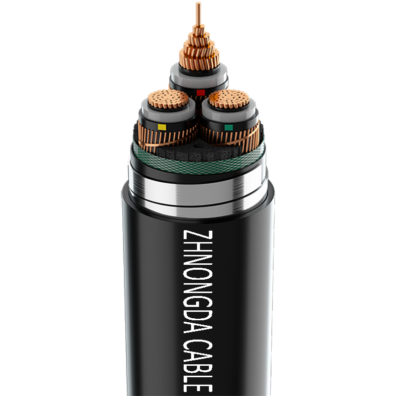
The conductor core carries the electrical current. Manufacturers typically use stranded copper or aluminum. Copper offers superior electrical conductivity and a smaller cross-section for a given ampacity. Aluminum provides a lighter, more cost-effective alternative, though it requires a larger overall cable diameter. For large cross-section cables exceeding 1000mm², engineers utilize Milliken (segmental) conductor designs. This specialized construction divides the conductor into insulated segments, often using a light enamel coating on the individual wires. It effectively reduces the skin effect and proximity effect, ensuring uniform current distribution across massive core diameters. Without the Milliken design, AC current would crowd the outer edges of the conductor, wasting the center mass and drastically reducing the effective ampacity.
An inner semi-conductive screen surrounds the conductor core. This extruded layer serves a critical function in electrical field management. It smooths the electrical field at the interface between the metallic conductor and the dielectric insulation. Without this screen, the stranded surface of the conductor would create localized electrical stress concentrations. These stress points would rapidly degrade the insulation and cause premature failure. The semi-conductive material is typically a blend of cross-linked polymer heavily loaded with carbon black to ensure it conducts just enough to equalize the voltage potential across the uneven surface of the wire strands.
Cross-Linked Polyethylene (XLPE) forms the primary dielectric barrier. A modern XLPE high voltage cable relies on this material for its exceptional dielectric strength and thermal stability. XLPE safely supports continuous operating temperatures up to 90°C and can withstand short circuit temperatures up to 250°C. Its solid dielectric nature requires virtually no maintenance. This reliability explains why XLPE has largely replaced older fluid-filled paper insulation systems in modern grid infrastructure. The manufacturing process requires extensive degassing. After extrusion, the cable sits in heated chambers for weeks to allow methane and other volatile byproducts of the cross-linking process to diffuse out of the insulation. If skipped, these gases can cause catastrophic pressure build-ups in the splice joints.
The outer semi-conductive screen encases the XLPE insulation. This layer works in tandem with the inner screen to control electrical stresses. It ensures that the electric field remains uniform and strictly radial. By confining the electrical field entirely within the XLPE insulation, the outer screen prevents external environmental factors from interfering with the cable's dielectric performance. It is co-extruded simultaneously with the inner screen and the XLPE layer in a single pass through the crosshead to ensure absolute bonding and zero air gaps between the layers.
A metallic sheath surrounds the outer semi-conductive screen. Manufacturers construct this sheath from extruded lead, corrugated aluminum, or copper wires with a foil laminate. The sheath serves a dual purpose. First, it provides a low-resistance path for fault current return, ensuring grid safety during short circuits. Second, it acts as a robust radial moisture barrier. It prevents water ingress, which would otherwise cause water treeing and dielectric breakdown within the XLPE layer. Lead is highly resistant to corrosion and water penetration but is heavy and prone to fatigue from vibration. Corrugated aluminum is lighter and handles mechanical stress better, making it common in modern terrestrial installations.
The external polymeric sheath provides the final layer of defense. Manufacturers typically use High-Density Polyethylene (HDPE) or Polyvinyl Chloride (PVC). This jacket focuses on mechanical protection against abrasion, impacts, and environmental degradation during the pulling process. Engineers often specify anti-termite and anti-rodent additives for direct-buried routes. Many jackets feature semi-conductive graphite coatings to facilitate outer sheath integrity testing after installation. For challenging environments like subsea interconnectors, designers add heavy galvanized steel wire armoring, sometimes in double counter-rotating layers, to withstand severe dynamic mechanical stress and anchor snags.
The grid industry relies on specific voltage ranges to categorize transmission infrastructure. An extra high voltage cable typically operates between 230 kV and 345 kV. In contrast, a UHV power cable handles extreme capacities, operating at 400 kV, 500 kV, and above. Legacy documentation sometimes refers to both categories broadly as high-tension (HT) cables. Modern engineering requires precise distinction due to the vastly different insulation thicknesses, degassing times, and manufacturing tolerances required. A 500 kV cable might have an insulation wall thickness exceeding 30mm, making it incredibly stiff and difficult to handle on site compared to a 230 kV line.
Underground UHV and EHV cables drastically reduce the spatial requirements of transmission networks. Traditional overhead lines demand massive land corridors to maintain safe clearance distances, often requiring clear-cutting forests and restricting land use beneath the towers. Securing this right-of-way incurs exorbitant land acquisition costs and faces heavy environmental opposition. Underground cables require a significantly narrower trench footprint. This compact profile allows grid planners to route massive power capacities through densely populated urban areas and environmentally sensitive zones. However, the joint bays for UHV cables are massive underground concrete vaults, sometimes 10 meters long, required every 600 to 1000 meters depending on the maximum pull tension the cable can withstand.
Evaluating the capital expenditure of UHV over EHV requires a strict cost-to-benefit analysis. UHV cables demand higher upfront costs for manufacturing, specialized jointing, and rigorous testing. However, they transmit exponentially more power with lower resistive losses. Planners justify UHV investments based on transmission distance and total load capacity. Over long routes with massive power blocks, the lifecycle energy savings and reduced infrastructure footprint of UHV heavily outweigh the initial capital premium. If a grid needs to move 2000 MW over 50 kilometers, doing so at 230 kV would require multiple parallel cable circuits, vastly increasing trenching costs. Stepping up to 500 kV allows the same power to flow through a single circuit.
| Parameter | Extra High Voltage (EHV) Cable | Ultra High Voltage (UHV) Cable |
|---|---|---|
| Typical Voltage Range | 230 kV to 345 kV | 400 kV, 500 kV, and above |
| Insulation Thickness | 15mm to 25mm | 27mm to 35mm+ |
| Manufacturing Method | CCV or VCV | Strictly VCV (Vertical Continuous Vulcanization) |
| Joint Bay Spacing | 800m to 1200m | 500m to 800m (due to drum weight limits) |
| Degassing Time | 1 to 2 weeks | 3 to 6 weeks |
The primary failure points in UHV systems are rarely the factory-produced cables. Splices and terminations represent the weakest links. UHV cable jointing requires extreme precision and surgical cleanliness. Jointers work inside climate-controlled habitats built over the joint bays to control humidity and dust. Microscopic impurities, a single stray fiber from clothing, or tiny air voids introduced during splicing distort the electrical field. These imperfections lead to partial discharge, which slowly erodes the insulation and eventually causes catastrophic system failure. A single 500 kV joint can take a highly specialized crew over a week to prepare, assemble, and test.
Underground routing introduces severe civil engineering challenges. The surrounding soil must absorb and dissipate the heat generated by the cable. Soil thermal resistivity, trench depth, and proximity to other utilities directly impact this thermal dynamic. If a specific section of the route features dry, highly resistive soil, it creates a thermal bottleneck. Engineers must often import specialized thermal backfill materials to ensure uniform heat dissipation along the entire route. We also have to space the phases appropriately. Laying the three phases in a flat formation dissipates heat better but requires a wider trench and induces higher circulating currents in the sheaths compared to a tight trefoil formation.
Offshore wind connections and international subsea interconnectors present unique installation risks. Subsea deployments require specialized cable-laying vessels and deep seabed trenching equipment like Remotely Operated Vehicles (ROVs) equipped with water jets. The cables endure severe dynamic mechanical stress from ocean currents and vessel tensioners during installation. Subsea jointing operations demand highly controlled environments aboard rolling ships, adding immense complexity to the splicing process. Pulling the cable through J-tubes onto offshore substation platforms requires precise tension monitoring to avoid stretching the copper core or damaging the lead sheath.
UHV maintenance demands extreme safety protocols. Grid operators rely on sophisticated protective relays to trip circuit breakers and clear faults instantly. Physical safety procedures are non-negotiable. Before any physical handling, crews must verify the cable is completely de-energized. Technicians utilize remote spiking techniques with hydraulic cutters. A hydraulic cutter will always cut all the way through the core. If the cable remains live, this action safely trips the protective device without endangering the operator. Induced voltages from parallel live circuits can also be lethal, requiring heavy-duty grounding sets applied at multiple points before work begins.
Mandatory site acceptance testing (SAT) procedures validate the installation before energization. High Voltage AC (HVAC) resonance testing applies elevated voltages to stress the insulation and verify its integrity. We use variable frequency resonant test sets because standard 50Hz or 60Hz testing would require impossibly large power supplies to overcome the cable's capacitance. Continuous Partial Discharge (PD) monitoring is critical during these tests. PD sensors detect microscopic electrical breakdowns within the splices or cable body, allowing engineers to identify and rectify defects before they cause operational failures. Passing the SAT is the final hurdle before handing the asset over to the grid operator.
Buyers must rigorously audit the manufacturer's extrusion process. UHV cables require absolute purity in the XLPE layer. Leading manufacturers utilize Vertical Continuous Vulcanization (VCV) lines. The vertical extrusion process prevents gravity from distorting the heavy, thick insulation while it cures. This ensures perfect concentricity and eliminates the risk of microscopic voids that plague horizontal or catenary extrusion methods at these voltage levels. VCV towers are massive structures, often exceeding 100 meters in height, representing a massive capital investment by the manufacturer.
Technical evaluation relies on non-negotiable industry standards. IEC 62067 dictates the strict testing and performance criteria for cables operating above 150 kV up to 500 kV. Manufacturers must also comply with relevant IEEE standards for specific regional deployments. Verifying compliance through independent, third-party type test certificates is mandatory before shortlisting any vendor. A proper type test for a 500 kV system includes a pre-qualification test that runs for an entire year, subjecting the cable and joints to continuous thermal cycling and elevated voltages to simulate decades of field aging.
Procurement teams must evaluate the risk mitigation benefits of vendor selection. Selecting vendors who provide integrated turnkey services offers significant advantages. These vendors handle manufacturing, specialized logistics, installation, and jointing under a single warranty umbrella. Supply-only vendors provide the raw cable spool but leave the immense risk of splicing and installation to third-party contractors. Turnkey solutions drastically reduce finger-pointing in the event of a post-installation failure. If a joint blows during commissioning, a turnkey provider must fix it. If you split the contracts, the cable supplier will blame the jointer, and the jointer will blame the cable manufacturer.
An ultra high voltage power cable is a highly engineered system where material science and installation precision are inseparable. The decision to utilize UHV is dictated by the mathematical necessity of moving massive loads over long distances with a minimal physical footprint. Upgrading infrastructure requires meticulous planning, strict vendor auditing, and flawless execution during the jointing and trenching phases. Decision-makers must prioritize vendors based on verifiable manufacturing tolerances, specifically those utilizing VCV extrusion lines. You must demand proven track records in high-voltage jointing and comprehensive partial discharge testing capabilities. The success of a macro-grid project relies entirely on the integrity of its weakest splice.
A: An ultra high voltage power cable generally starts at 400 kV and extends to 500 kV, 800 kV, and above. This distinguishes it from lower voltage tiers like extra high voltage (230 kV to 345 kV) and standard high voltage distribution systems.
A: No. While EVs and residential distribution use systems labeled as "high voltage" (typically 400V to 1000V for EVs, and up to 35kV for local distribution), UHV cables operate at 400,000V and above. They are strictly designed for macro-grid transmission and major substations.
A: An XLPE high voltage cable utilizes a solid dielectric made of Cross-Linked Polyethylene. This solid insulation requires virtually no maintenance. In contrast, older fluid-filled paper cables rely on complex oil pumping systems that present significant environmental leak risks and high maintenance demands.
A: The difference lies in technical thresholds and capacity. Extra high voltage (EHV) typically covers 230 kV to 345 kV. UHV handles much higher capacities (400 kV+), which requires significantly thicker insulation, stricter VCV manufacturing tolerances, and more complex jointing procedures.
A: Semi-conductive screens smooth the electrical field between the conductor, the insulation, and the metallic sheath. They prevent localized voltage stress concentrations that would otherwise rapidly degrade the dielectric insulation and cause premature cable failure.
A: Partial discharge is caused by microscopic voids, moisture ingress, or dust impurities trapped within the insulation or splice joints. These defects create localized electrical breakdowns that slowly erode the surrounding dielectric material over time.
A: AC underground cables face strict distance limitations due to capacitive charging currents. Over long distances, the cable draws reactive current that consumes its ampacity. High Voltage Direct Current (HVDC) is typically required for extremely long underground or subsea transmission routes.
 简体中文
简体中文 

