

Views: 0 Author: Site Editor Publish Time: 2026-08-14 Origin: Site


Reliable power transmission forms the physical backbone of all commercial, industrial, and IT infrastructure. Yet, the actual mechanics of power delivery often get overlooked during hardware procurement. Specifying the wrong power cord based on a superficial understanding of its internal mechanics leads to thermal overload, unacceptable voltage drop, equipment failure, and severe safety violations. You must evaluate the electrical load, environmental conditions, and routing distance before selecting a cable for any installation.
Understanding exactly how an AC Power Cable transmits energy enables engineers and procurement teams to evaluate specifications accurately. From electron flow to conductor anatomy, connector standards, and insulation properties, every component matters in the field. This knowledge allows you to mitigate implementation risks, avoid code violations, and select the exact cable architecture required for your specific operational load.
To evaluate a cable's capacity, you must first understand the nature of the electrical load it carries. Alternating current operates on a fundamental mechanism where electrons oscillate back and forth. They do not flow continuously in one direction like direct current. This rapid oscillation transfers energy efficiently over long distances, minimizing power loss across the grid. The sine wave generated by the power source dictates how the voltage peaks and crosses zero multiple times per second.
An alternating current cable requires specific insulation dielectric strengths and stranding configurations compared to DC cables. This difference stems primarily from continuous voltage fluctuation and the potential for capacitive coupling. When voltage constantly changes, the insulation must withstand the absolute peak of the sine wave, not just the RMS (Root Mean Square) average. Regional grid standards heavily impact cable design. North America operates on 120V/60Hz, while Europe uses 240V/50Hz. These standards dictate specific dielectric strength requirements and connector configurations to maintain safety across different distribution panels.
At higher frequencies, alternating current tends to flow near the surface of a conductor. This phenomenon is known as the skin effect. While less pronounced at standard 50Hz or 60Hz frequencies compared to radio frequencies, this physical reality still influences the choice between solid and stranded wire in specific high-amperage cable designs. Stranded wire mitigates resistance increases caused by the skin effect by providing more surface area. It also makes the cable highly suitable for flexible power cords that require tight bending radii in server racks or machinery enclosures.
When routing power through industrial facilities, you must account for the magnetic fields generated by alternating current. As the current reverses direction, the expanding and collapsing magnetic fields can induce currents in nearby conductive materials. This requires careful consideration of conduit materials and spacing to prevent inductive heating. Field engineers often use twisted pair configurations or specific shielding techniques to cancel out these magnetic fields in sensitive environments.
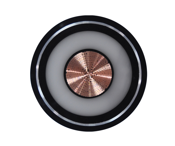
Breaking down the physical layers and endpoints of the cable helps you understand how each component contributes to safe power delivery. The core conductor material plays a massive role in overall performance. Oxygen-free copper is the standard for most flexible cords due to its high conductivity, low resistance, and excellent tensile strength. Copper withstands repeated flexing without breaking. Aluminum is often used in fixed, high-capacity utility routing because it is lighter and more cost-effective. However, aluminum requires larger diameters to match copper's ampacity and demands specialized anti-oxidant compounds at termination points to prevent galvanic corrosion and thermal runaway.
Wire configurations determine the safety and functionality of the circuit. A 2-wire system lacks a dedicated ground, while a 3-wire system includes one. In commercial installations, the 3-wire system is the absolute minimum standard for equipment safety.
Insulation materials isolate the conductors from each other and the outside world. They prevent arcing and determine the cable's maximum voltage rating. PVC (Polyvinyl Chloride) is common for standard indoor use. XLPE (Cross-linked Polyethylene) offers superior thermal resistance and is used in high-voltage or high-temperature industrial settings. EPR (Ethylene Propylene Rubber) provides excellent flexibility and dielectric strength, often found in heavy-duty mining or welding cables.
The outer jacketing protects these internal mechanics from moisture, UV exposure, chemical degradation, and physical abrasion. A cable routed across a factory floor requires a much tougher jacket than one sitting behind an office desk. Materials like polyurethane or thermoset rubber provide the necessary mechanical defense against forklift traffic, oil spills, and extreme weather.
Connector and plug terminations form the mechanical interfaces of the cable. You must differentiate between North American NEMA standards (e.g., 5-15P, L6-30P) and international IEC 60320 standards (e.g., C13/C14, C19/C20). NEMA locking connectors (the "L" series) are standard in industrial environments to prevent accidental disconnection. IEC connectors are ubiquitous in IT hardware, allowing manufacturers to ship the same server globally and simply swap the localized power cord in the box.
| Component Layer | Common Materials | Field Application & Function |
|---|---|---|
| Conductor Core | Bare Copper, Tinned Copper, Aluminum | Transmits the electrical current. Tinned copper resists corrosion in marine environments. |
| Primary Insulation | PVC, XLPE, EPR, THHN | Isolates conductors. XLPE is used for high-heat industrial routing. |
| Shielding (Optional) | Aluminum Foil, Tinned Copper Braid | Blocks EMI/RFI. Essential for cables routed near sensitive data lines. |
| Outer Jacket | SJT, SOOW, Polyurethane | Provides environmental defense. SOOW resists oil and water in harsh conditions. |
| Terminations | NEMA 5-15, IEC C13, Pin & Sleeve | Ensures secure mechanical mating. Pin & Sleeve used for high-amp industrial loads. |
Translating internal cable mechanics into procurement specifications requires careful evaluation of the installation environment. The American Wire Gauge (AWG) system defines physical wire diameter in North America. There is an inverse relationship between AWG numbers and wire thickness. A lower AWG number means a thicker wire, which carries higher amperage. You must match the AWG to the required amperage load to prevent overheating an AC electrical cable. For example, a 14 AWG wire is typically rated for 15 amps, while a 12 AWG wire handles 20 amps. Pushing 20 amps through a 14 AWG cord will cause the insulation to melt, leading to a dead short.
Voltage ratings and insulation thickness dictate the dielectric strength of a cable. This ensures the cable can handle peak voltage spikes without insulation breakdown. A cable rated for 300V (like an SVT cord) is fine for standard desktop computers. However, industrial machinery operating on 480V requires cables rated for 600V or 1000V to provide an adequate safety margin against transients and motor startup surges.
Ambient temperature heavily affects ampacity. High temperatures require derating the cable's capacity. If you route a cable through a hot ceiling space or a boiler room, the copper cannot dissipate heat as effectively. The National Electrical Code (NEC) provides specific derating tables for these scenarios. You must evaluate cables for extreme environments, specifying jacket types like SJT for light indoor use or SOOW for harsh, wet, or oily conditions.
Understand the mechanical and regulatory distinctions between permanent equipment power supply cords and temporary extension cables. Extending power over longer temporary distances requires specific derating factors to account for voltage drop and increased resistance. A 100-foot extension cord running a heavy power tool must be at least 10 AWG to prevent voltage drop from burning out the tool's motor. Permanent installations require hardwiring or specific receptacle types, not daisy-chained extension cords.
Aligning cable construction with specific industry use cases ensures operational stability and code compliance. In data centers and IT infrastructure, C13/C14 and C19/C20 jumper cords are standard. You must focus on the mechanics of high-density power distribution. Airflow considerations and strict length management are necessary to minimize voltage drop across server racks. Excess cable length blocks exhaust fans and creates unnecessary resistance. Data center managers often specify exact-length, color-coded cables to map redundant A/B power feeds visually.
Industrial machinery requires heavy-duty cables. These environments demand resistance to oil, water, and mechanical stress. Locking connectors and reinforced jacketing are standard requirements for these AC cable applications. Variable Frequency Drives (VFDs) require specialized shielded cables to handle the high-frequency noise and voltage spikes generated by the drive. Standard unshielded cables will fail rapidly in a VFD application due to corona discharge breaking down the insulation.
Medical environments require "Hospital Grade" (Green Dot) cables. These feature enhanced grounding reliability, rigorous plug retention force testing, and durability under frequent physical stress. The grounding pin on a hospital-grade plug is solid rather than folded, ensuring a low-resistance path even if the plug is yanked from the wall repeatedly. This prevents micro-shocks that could be fatal to patients connected to sensitive monitoring equipment.
Standard consumer appliance cords feature lightweight, unshielded construction. They are designed for static environments with minimal physical hazards. In contrast, enterprise hardware often requires robust, shielded cables to protect against interference and physical damage. Outdoor installations demand UV-resistant jacketing to prevent the plasticizers from leaching out, which would cause the cable to become brittle and crack under sunlight exposure.
When cable mechanics fail to meet operational demands, the results range from intermittent equipment reboots to catastrophic facility fires. You must verify integrity before deployment. Pre-installation testing using a digital multimeter or a megohmmeter (Megger) is a critical field practice. Perform continuity testing to ensure no internal breaks exist in the conductors. Verify hot/neutral polarity. Reversed polarity energizes the chassis of older equipment, creating a severe shock hazard for operators.
Voltage drop over long distances is a physical reality governed by Ohm's Law. As wire length increases, resistance increases. You must calculate acceptable voltage drop (typically keeping it under 3% for branch circuits) and mitigate it by up-sizing the conductor gauge. If a 20-amp load is 150 feet away from the panel, standard 12 AWG wire will result in too much voltage drop. You must up-size to 10 AWG to maintain the proper voltage at the load.
Subjecting a cable to an amperage exceeding its AWG rating leads to thermal overload. The mechanical failure chain starts with the copper heating up. The heat transfers to the insulation, causing it to soften, deform, and eventually melt. Once the hot and neutral conductors touch, a massive short circuit occurs, potentially igniting surrounding materials before the breaker has time to trip.
Unshielded power cables can induce electromagnetic interference (EMI) in adjacent low-voltage data cables. If you run a 480V power line parallel to a Cat6 network cable, the magnetic field from the power line will corrupt the data packets. Specify shielded cables with foil or braided shielding to mitigate this risk in dense server racks or sensitive environments. Always maintain proper physical separation (usually at least 12 inches) between high-voltage power and low-voltage data lines.
Ensuring the selected mechanics meet legal and safety frameworks is non-negotiable for any commercial installation. Independent testing laboratories like UL (Underwriters Laboratories), CSA (Canadian Standards Association), and IEC (International Electrotechnical Commission) verify a cable's internal construction. They subject cables to rigorous testing for flame retardance, crush resistance, and electrical safety. Always check for these certification marks printed directly on the cable jacket. Using unlisted cables violates the National Electrical Code and voids facility insurance policies.
Environmental and workplace safety compliance is also critical. Evaluate the chemical composition of the cable's insulation and jacketing for RoHS (Restriction of Hazardous Substances) and REACH compliance. This ensures the materials do not contain restricted heavy metals like lead or cadmium. In plenum spaces (areas used for building airflow), you must use plenum-rated cables (like CMP). These cables use specialized insulation that emits low smoke and zero halogens (LSZH) when burned, preventing toxic gas from spreading through the HVAC system during a fire.
An AC power cable is a highly engineered conduit whose internal mechanics dictate the safety and reliability of connected equipment. Procurement decisions must be driven by a strict evaluation of required ampacity, environmental conditions, and regulatory standards. Ignoring these physical realities leads to system downtime and safety hazards.
A: AC cables handle continuous voltage fluctuation and oscillating electron flow. They feature different insulation dielectric strengths and stranding configurations compared to DC cables to manage capacitive coupling and the skin effect. DC cables deal with constant voltage and unidirectional flow, requiring different insulation grading.
A: You determine the correct AWG by calculating the maximum continuous amperage load of the connected equipment. Cross-reference this load with standard NEC ampacity charts, factoring in ambient temperature derating and total cable length to prevent overheating and voltage drop.
A: A 2-wire cable lacks a dedicated ground path. If a mechanical fault occurs and the metal chassis becomes electrified, there is no low-resistance return path for the fault current to trip the breaker. This significantly increases the risk of fatal electrocution.
A: Use a digital multimeter set to the continuity function. Probe the corresponding prongs on the plug and the connector to ensure an unbroken electrical path. Verify that the hot prong connects only to the hot terminal to confirm correct polarity.
A: Yes. The oscillating current in unshielded AC cables generates an electromagnetic field. If routed too closely to low-voltage data cables, this field induces interference, corrupting data transmission. Shielded cables and proper physical separation mitigate this issue.
A: Voltage drop becomes significant when cable runs exceed 50 to 100 feet, depending on the wire gauge and the amperage load. Up-sizing the AWG reduces resistance and mitigates voltage drop over longer distances, keeping it within the recommended 3% limit.
 简体中文
简体中文 

