

Views: 0 Author: Site Editor Publish Time: 2026-08-27 Origin: Site


Catastrophic failures in high-voltage utility and industrial networks lead to severe operational disruptions and massive financial losses. Traditional scheduled maintenance programs often fail to catch unpredictable issues like insulation degradation, thermal breakdown, and partial discharge before they cause an outage. Relying solely on periodic checks leaves infrastructure vulnerable to sudden faults.
Continuous High Voltage Cable Monitoring replaces this reactive approach with predictive maintenance. By capturing real-time data on cable health, operators can identify anomalies early and schedule repairs without unplanned downtime. Technical evaluators must carefully assess sensor sensitivity, data transmission, and system scalability when selecting a monitoring solution to protect critical grid assets.
Reliable monitoring systems must deliver early fault warnings with minimal false positives. Success depends on capturing actionable data that operators can use to make immediate maintenance decisions. A functional system filters out ambient electrical noise and isolates genuine indicators of insulation stress. The goal is to provide a clear, accurate picture of cable integrity under continuous load.
Field technicians evaluate success based on the signal-to-noise ratio (SNR) achieved by the sensor array. High-voltage environments generate significant electromagnetic interference (EMI) from nearby transformers, switchgear, and overhead lines. A successful monitoring deployment utilizes advanced filtering algorithms to separate this background noise from actual discharge events. Operators need confidence that an alarm represents a physical defect in the cable, not a transient spike from grid switching operations.
Another metric for success is the system's ability to classify the type of defect. Different insulation issues produce distinct discharge patterns. For example, internal voids within cross-linked polyethylene (XLPE) insulation generate different phase-resolved partial discharge (PRPD) patterns compared to surface tracking on a cable termination. A robust system identifies the defect type, allowing maintenance crews to prepare the correct replacement parts before arriving on site.
Partial discharge occurs when localized electrical stress breaks down a small portion of solid or fluid insulation. In high-voltage cables, these microscopic discharges are the primary leading indicator of impending insulation failure. Over time, PD erodes the dielectric material, eventually causing a complete short circuit.
Detecting these discharges presents significant physical challenges. High-frequency discharge signals attenuate rapidly as they travel along the cable shield. To capture these faint signals, technicians must install high-frequency current transformers (HFCT) or capacitive sensors directly at cable joints and terminations. Precise sensor placement near the expected discharge source is mandatory to maintain signal integrity and achieve high detection sensitivity.
The physics of signal attenuation dictate network design. A discharge pulse originating in a cable joint might have a bandwidth extending up to several hundred megahertz. As this pulse travels through the semi-conductive layers and the metallic shield of the cable, the high-frequency components dissipate as heat. By the time the signal travels a few hundred meters, only the lower frequency components remain, making it difficult to distinguish from background noise. This physical limitation requires distributed sensor architectures where measurement nodes are installed at every splice and termination along the cable route.
Monitoring phase current, screen current, and localized temperatures provides a complete view of operational health. Excessive screen currents often indicate grounding issues or circulating currents that generate unwanted heat. Tracking joint temperatures helps identify localized hotspots caused by poor connections or overloaded circuits.
Thermal anomalies correlate directly with accelerated insulation aging and impending faults. When a system detects an abnormal temperature rise, it triggers an alert. Modern systems integrate remote video monitoring at critical junctions. This allows operators to visually inspect physical conditions, such as fluid leaks or structural damage, immediately after receiving an emergency thermal alert.
Distributed Temperature Sensing (DTS) utilizes fiber optic cables installed alongside or within the power cable to measure temperature profiles over long distances. By analyzing the Raman scattering of laser light pulsed through the fiber, the system calculates the exact temperature at any point along the cable run. This continuous thermal map allows operators to dynamically rate the cable, pushing more current during peak demand if the ambient soil conditions permit adequate cooling.
| Monitoring Parameter | Sensor Technology | Primary Defect Detected | Actionable Outcome |
|---|---|---|---|
| Partial Discharge | HFCT, Capacitive Couplers | Insulation voids, electrical treeing | Schedule joint replacement before failure |
| Temperature | DTS (Fiber Optic), Thermocouples | Overloading, poor contact resistance | Adjust load dynamically, inspect connections |
| Screen Current | Standard Current Transformers | Sheath faults, grounding degradation | Repair outer jacket, restore grounding integrity |
| Visual Condition | Remote IP Cameras | Physical damage, fluid leaks, intrusion | Dispatch emergency response team |
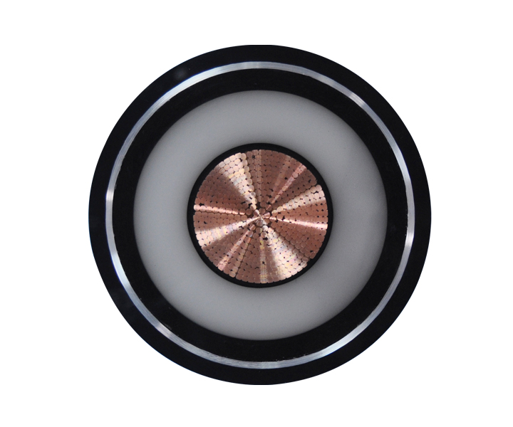
Automatic On-Line Cable Monitoring (AOLCM) systems capture data while the power grid remains fully energized. These systems evaluate insulation health without requiring power outages. By tracking parameters under actual load and environmental conditions, operators gain an accurate representation of how the cable performs during peak demand.
Continuous cable condition monitoring identifies transient events that only occur at specific operating temperatures or voltage levels. This real-time visibility is essential for preventing sudden failures in highly stressed transmission lines. Certain defects, such as those caused by thermal expansion in cable joints, only manifest when the cable carries maximum load. Offline testing at ambient temperatures completely misses these load-dependent discharge events.
Implementing an online system requires careful integration with existing substation infrastructure. The monitoring hardware must withstand high transient overvoltages and harsh environmental conditions. Data acquisition units installed in underground vaults need IP68-rated enclosures to survive flooding. The communication network must reliably transmit high-bandwidth PRPD data back to the central server without dropping packets during grid switching events.
Offline testing requires disconnecting the cable from the grid. Technicians use this scheduled downtime to establish baseline metrics and perform deep-dive diagnostics. Common offline techniques include Very Low Frequency (VLF) testing and Tan Delta (Dissipation Factor) measurements. These tests apply controlled voltage stress to identify global insulation degradation and moisture ingress.
Operators must balance operational trade-offs. Continuous online monitoring provides uninterrupted visibility and immediate fault alerts. Offline testing offers a controlled, high-stress diagnostic environment to assess overall dielectric health. A robust maintenance strategy utilizes both methods to ensure complete network reliability.
When executing high voltage cable diagnostics offline, field crews typically follow a strict sequence of operations to ensure safety and data accuracy:
While offline testing provides excellent baseline data, it requires significant labor and operational downtime. Utilities reserve these tests for commissioning new cables or investigating specific circuits that have shown warning signs during online monitoring.
Monitoring systems utilize either passive or active sensors. Passive sensors require no external power, offering high reliability and zero maintenance. However, they typically provide less complex data processing at the measurement point. Active sensors deliver advanced localized analytics but require a stable power source.
Powering active sensors in remote or underground locations is challenging. Many systems use power harvesting methods to eliminate the need for external batteries. Toroidal units clamped directly onto the high-voltage power line extract energy from the magnetic field. This Power Supply System (PPS) provides continuous, reliable energy to the monitoring hardware as long as the cable carries current.
When load currents drop below the threshold required for power harvesting, active systems rely on backup supercapacitors or lithium-ion batteries to maintain operation. Designing a reliable power architecture is critical for underground vaults where running dedicated low-voltage supply lines is physically impossible or prohibitively expensive. The power harvesting CT must be sized correctly to match the expected minimum load current of the specific cable circuit.
Robust data backhaul is required to move raw sensor data to central control rooms. Systems rely on wireless communication, fiber optics, or 3G/4G networks to transmit information. In emergency scenarios, 3G remote video feeds provide immediate visual confirmation of physical damage at cable joints.
Analytics platforms process this incoming data to enable rapid cable fault detection. The software applies algorithms to filter out ambient electrical noise and isolate true partial discharge events. This translation of raw data into actionable insights allows maintenance teams to pinpoint fault locations accurately.
Edge computing plays a growing role in modern monitoring architectures. Instead of transmitting gigabytes of raw high-frequency waveforms over cellular networks, the local data acquisition unit processes the signals on-site. The edge device calculates the PRPD patterns, extracts key features, and only transmits the compressed diagnostic data and alarm triggers to the central server. This approach drastically reduces bandwidth requirements and ensures reliable operation even in areas with poor cellular coverage.
When selecting a monitoring system, map specific hardware features to desired operational outcomes. High-frequency PD sensors directly reduce unplanned downtime by catching insulation defects early. Real-time thermal alerts optimize maintenance schedules by directing crews only to overheating joints. Passive sensor reliability lowers the total maintenance burden of the monitoring system itself.
A utility struggling with frequent joint failures on an aging 110kV network should prioritize high-sensitivity HFCTs and advanced noise filtering. Conversely, an industrial facility managing heavily loaded 33kV feeder cables might prioritize DTS thermal monitoring to safely maximize current throughput without exceeding the cable's thermal limits. Aligning the technology with the specific failure modes of the network ensures a successful deployment.
A monitoring architecture must scale easily across extensive underground and overhead networks. The same core technology used for ultra-high-voltage transmission lines should adapt to medium voltage infrastructure. Implementing monitoring on networks up to 6 kV ensures comprehensive coverage across the entire distribution grid. All deployed hardware must comply with strict industry safety and dielectric testing standards.
Scaling a system requires standardized communication protocols. Hardware from different vendors must integrate seamlessly into the utility's central SCADA system using protocols like IEC 61850 or DNP3. Proprietary, closed-loop systems force operators to monitor multiple separate dashboards, increasing the risk of missed alarms. A scalable solution aggregates data from 220kV transmission lines down to 6kV distribution feeders into a single, unified diagnostic platform.
Installing sensors and video equipment in harsh, confined underground vaults presents physical challenges. Technicians must ensure proper grounding and secure mounting to withstand environmental stress. Data overload is another significant risk. Analytics platforms must feature robust noise-filtering algorithms. Properly configured software prevents false alarms caused by external electromagnetic interference, ensuring operators only respond to genuine threats.
Water ingress is the primary enemy of underground monitoring hardware. Splice vaults frequently flood, submerging sensors and data acquisition units. Mitigation requires specifying IP68-rated enclosures and utilizing waterproof connectors for all sensor cables. Additionally, the installation team must carefully route fiber optic and coaxial cables to prevent mechanical damage from rodents or future maintenance activities in the vault.
Grounding the monitoring equipment correctly is vital for both safety and signal integrity. Improper grounding loops introduce massive amounts of 50/60Hz noise into the measurement circuit, completely masking the high-frequency discharge signals. Field crews must follow strict grounding procedures, ensuring the sensor shields are bonded to the main earth grid at a single point to prevent circulating currents.
Integrating partial discharge, thermal, and visual tracking provides operators with the necessary tools to manage modern high-voltage networks safely. Shifting from reactive repairs to continuous condition monitoring prevents catastrophic failures and extends asset lifespans. Implementing these systems requires careful planning, precise sensor installation, and robust data integration.
A: Online diagnostics monitor cable health continuously while the system is energized and under normal load. Offline diagnostics require de-energizing the cable to apply controlled test voltages, such as VLF or Tan Delta, to assess overall insulation condition.
A: Partial discharge is a localized electrical breakdown within the insulation. It creates small sparks that slowly erode the dielectric material. Detecting these discharges provides an early warning that the insulation is failing before a complete short circuit occurs.
A: High-frequency signals generated by partial discharge attenuate very quickly as they travel along the cable. Sensors must be installed as close to the potential discharge source, such as joints or terminations, to capture the signal accurately.
A: Many active sensors use power harvesting technology. Toroidal current transformers clamp around the high-voltage cable and extract energy from the surrounding magnetic field, providing continuous power without relying on external batteries.
A: Systems track high-frequency partial discharge signals, phase current, screen current, and localized temperatures at cable joints. Abnormal spikes in any of these parameters indicate potential insulation stress or impending failure.
A: Signal attenuation weakens the high-frequency pulses as they move away from the fault location. If sensors are placed too far away, the signal will degrade into background noise, causing the monitoring system to miss critical partial discharge events.
 简体中文
简体中文 

