

Views: 0 Author: Site Editor Publish Time: 2026-08-30 Origin: Site


Underspecifying cabling in harsh environments introduces severe operational and financial risks. Catastrophic equipment failure, unplanned downtime, fire hazards, and compliance violations often stem from inadequate conductor sizing or improper insulation. Facility managers and electrical engineers navigate a complex matrix of electrical demands, environmental stressors, and strict regulatory codes daily. Selecting the wrong cable inevitably leads to premature degradation, excessive voltage drop, or costly rework. We provide a systematic, engineering-aligned framework for evaluating and specifying the exact Industrial Power Cable required for specific facility demands. This guide balances performance and safety while ensuring long-term reliability. You must account for peak loads, thermal limits, and mechanical wear to prevent system failure. Proper specification requires analyzing the entire electrical route, from the main breaker to the final machine termination.
Success in cable selection extends far beyond basic conductivity. You must ensure uninterrupted power delivery under peak load and worst-case environmental conditions. Facilities demand robust infrastructure that withstands continuous mechanical stress and thermal cycling. A cable that performs perfectly in a climate-controlled server room will fail rapidly when exposed to the cutting fluids, extreme heat, and constant vibration found on a manufacturing floor. You must define success by the system's ability to operate continuously without thermal degradation or signal interference.
Improper selection carries significant hidden costs. Undersized or improperly jacketed cables cause continuous energy loss through I²R heating. Insulation melting creates immediate short-circuit hazards. Premature replacement drives up labor costs and forces unplanned facility shutdowns. When a main feeder fails due to improper ampacity derating, the resulting downtime costs far exceed the initial savings of purchasing a smaller conductor. You must evaluate the long-term operational stability of the installation.
You must align material specifications with operational goals. Establish a rigid evaluation framework. Start with electrical requirements. Move to material specifications. Evaluate environmental stressors next. Finally, account for installation constraints. This sequential approach prevents critical oversights. For example, selecting a highly flexible cable is useless if the jacket material degrades upon contact with the specific hydraulic fluids used in your machinery.
Low-voltage distribution typically handles up to 1kV. Medium and high-voltage systems manage distribution across larger facility footprints, often operating at 5kV, 15kV, or 35kV. The cable voltage rating must always exceed the maximum operating voltage of the system. This buffer handles unexpected spikes and transient surges safely. Using a 600V rated cable on a system that experiences frequent 800V transients will cause rapid insulation breakdown and eventual dielectric failure.
Determine the maximum continuous current the connected equipment will draw. Apply strict safety margins during this calculation. The National Electrical Code often requires sizing conductors at 125% of the continuous load. Coordinate cable ampacity directly with Overcurrent Protection Devices (OCPD). Ensure the industrial electrical cable rating meets or exceeds standard breaker and fuse sizes. Never place undersized 10A cables on standard 20A industrial circuits. If a motor draws 40 amps continuously, the conductor must be rated for at least 50 amps, and the breaker must be sized to protect that specific conductor gauge.
Voltage drop occurs naturally over long cable runs due to inherent conductor resistance. Standard acceptable thresholds limit drop to 3% for branch circuits and 5% for overall feeders. Increasing the conductor size (AWG or kcmil) lowers resistance. Upsizing the conductor effectively mitigates unacceptable voltage drop over extended distances. When routing power to a remote pump station 500 feet away, a standard ampacity calculation might suggest a 4 AWG wire, but voltage drop calculations will often dictate upsizing to a 2 AWG or 1/0 AWG conductor to ensure the motor receives adequate voltage to start and run efficiently.
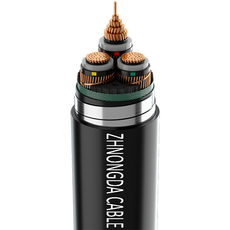
Copper offers superior conductivity, high flexibility, and lower electrical resistance. It remains the standard for compact spaces, though it carries higher weight and material costs. Aluminum provides a cost-effective, lightweight alternative for large-scale factory power cable runs. Aluminum requires larger cross-sections to match copper ampacity. It also demands specialized termination compounds to prevent oxidation and thermal creep. When terminating aluminum, you must use dual-rated (AL/CU) lugs and apply a high-quality oxide inhibitor to prevent high-resistance connections that can lead to thermal runaway.
| Material | Conductivity | Weight | Termination Requirements | Primary Use Case |
|---|---|---|---|---|
| Copper | Excellent | Heavy | Standard lugs | Compact routing, high-flex applications, motor leads |
| Aluminum | Good (Requires Upsizing) | Light | Dual-rated lugs, oxide inhibitor | Long feeder runs, large-scale distribution, overhead lines |
Industrial insulations vary significantly in thermal and chemical resistance. Polyvinyl Chloride (PVC) offers basic protection for standard indoor environments but becomes brittle in extreme cold. Cross-linked Polyethylene (XLPE) provides excellent moisture resistance and handles 90°C operating temperatures, making it ideal for wet locations and direct burial. Ethylene Propylene Rubber (EPR) delivers superior flexibility and dielectric strength, often preferred in medium-voltage applications. Map your insulation choice directly to specific operating temperatures and environmental hazards. Thermoset insulations like XLPE and EPR will not melt under short-circuit conditions, unlike thermoplastic PVC.
High ambient heat reduces a cable's allowable ampacity. You must apply ambient temperature derating factors when routing through hot environments like boiler rooms or foundry ceilings. Evaluate jacketing materials for resistance to oil, solvents, acids, and UV radiation. Chlorinated Polyethylene (CPE) and Polyurethane excel in harsh industrial cable applications where chemical exposure is frequent. If a cable is routed across a rooftop, it must possess a sunlight-resistant rating to prevent the outer jacket from cracking and exposing the inner conductors to moisture.
Stationary routing requires different construction than continuous-flex applications. Robotics and gantry cranes demand specialized high-flex cables designed to withstand millions of bending cycles. Stranding classes dictate mechanical endurance. Class B stranding suits fixed installations. Class K or M stranding provides the necessary flex life for moving machinery. Using a stiff, Class B stranded cable on a moving drag chain will result in broken copper strands, localized heating, and eventual phase-to-phase faults.
Armored cables provide necessary crush resistance. Aluminum Interlocked Armor (AIA) or Steel Wire Armor (SWA) protects conductors from physical impacts and rodents. Use unarmored cables only when routing through fully protected, rigid conduits. In environments where heavy forklifts operate or where falling debris is a risk, armored cable eliminates the need for installing rigid steel conduit, saving significant labor time while maintaining high mechanical protection.
Installation methods directly affect heat dissipation. Open cable trays allow maximum airflow, permitting conductors to operate near their maximum ampacity. Direct burial and enclosed conduits trap heat. NEC requirements mandate ampacity derating when bundling multiple current-carrying conductors in a single raceway. If you place nine current-carrying conductors in a single conduit, you must derate their ampacity to 70% of their original value to prevent the trapped heat from melting the insulation.
Match the cable physical dimensions and conductor material to appropriate industrial lugs. The weakest link temperature rule governs final ampacity. A 90°C rated cable must often be ampacity-derated to 75°C if connected equipment terminals are only rated for 75°C. Always account for tight space constraints and bend radius limitations within junction boxes. Forcing a stiff, large-gauge cable into a small enclosure violates the minimum bend radius, stressing the insulation and potentially causing micro-cracks that lead to arc faults.
Variable Frequency Drives introduce high-frequency noise, severe voltage spikes, and potential corona discharge. Standard cables fail rapidly under these conditions. Specialized VFD cables utilize heavy shielding, such as copper tape or braid. They feature symmetrical ground designs to prevent motor bearing damage and contain Electromagnetic Interference (EMI). Without proper VFD cabling, the high-frequency switching of the drive can induce voltages in the grounding system, leading to premature failure of the motor bearings through electrical fluting.
Control cables handle low-current signals rather than heavy power loads. Signal integrity and shielding take precedence over ampacity. Foil shields and twisted pairs protect sensitive instrumentation data from adjacent power line interference. When routing control cables near heavy power feeders, you must maintain physical separation or use heavily shielded twisted pair (STP) cables to prevent inductive coupling from corrupting the low-voltage sensor signals.
Compliance ensures safety and operational legality. Critical standards include NEC, UL, CSA, and IEEE. Cross-reference all cable selections with OEM equipment manuals. Project engineering standards often dictate specific approvals. Non-compliance voids warranties, compromises facility insurance, and fails safety audits. Inspectors will immediately flag installations that use unlisted cables or fail to adhere to the specific routing and support requirements outlined in the National Electrical Code.
Unverified cables pose severe fire risks. Copper-clad aluminum is sometimes falsely marketed as pure copper. Fake UL stamps appear on substandard imports. Always request detailed spec sheets. Verify manufacturer track records and demand third-party testing certificates before procurement. Inspect the cable jacket upon delivery for proper print legends, including gauge, voltage rating, insulation type, and testing laboratory file numbers.
A: You calculate voltage drop using the load current, total route length, conductor resistance, and system voltage. Upsize conductors for long runs to keep the voltage drop below 3% for branch circuits and 5% for feeders.
A: XLPE offers superior moisture resistance, durability, and a higher temperature rating of 90°C or more. PVC provides a cost-effective, flexible solution suitable for less demanding, standard indoor environments.
A: Choose armored cables when facing high risks of physical impact, heavy crush hazards, or when routing without rigid conduit in exposed, heavy-duty industrial environments.
A: Higher ambient temperatures reduce the cable ability to dissipate internal heat. You must apply ampacity derating factors according to NEC tables to prevent insulation damage and fire hazards.
A: The NEC requires sizing cable ampacity based on the lowest temperature rating of any connected termination. This is typically 75°C. It prevents the terminal from overheating and failing under load.
A: VFD cables require robust shielding, typically copper tape or heavy braid, to contain EMI. They also need symmetrical ground designs to prevent stray currents from destroying motor bearings.
 简体中文
简体中文 

