

Views: 0 Author: Site Editor Publish Time: 2026-08-10 Origin: Site


Selecting an inadequate cable voltage rating is a primary catalyst for dielectric breakdown, leading to catastrophic equipment failure, severe safety hazards, and costly unplanned downtime. Engineers and procurement teams often struggle to balance strict electrical code compliance with project budgets. Undersizing risks immediate insulation failure, while arbitrary oversizing inflates material costs, increases cable outer diameters, and complicates installation routing.
Establishing a rigorous, evidence-based framework for specifying Cable Voltage Rating requires a step-by-step analysis of system voltages (Uo/U/Um), current load requirements, fault-clearing times, environmental stressors, and the specific demands of AC versus DC architectures. This guide breaks down the exact methodology needed to specify the right cable for industrial and commercial power systems.
International standards define cable voltage capabilities using a specific three-part designation: Uo/U/Um. Uo represents the RMS phase-to-ground voltage. U indicates the RMS phase-to-phase voltage. Um defines the maximum permissible continuous system voltage. Understanding these three values prevents catastrophic misapplication. You cannot simply look at a nominal 480V system and guess the requirement. You must match the cable's tested limits against the grid's maximum potential output under normal operating conditions. For example, a cable designated as 8.7/15 (17.5) kV means it is rated for 8.7 kV phase-to-ground, 15 kV phase-to-phase, and can withstand a maximum continuous system voltage of 17.5 kV. The mathematical relationship is fixed: Uo is typically U divided by the square root of 3 (Uo = U / √3) in three-phase systems.
Effective specification follows a strict foundational workflow. Skipping steps leads to field failures and code violations. Follow this sequence to ensure baseline compliance and operational reliability:
The mathematical relationship between system operating voltage and required cable rating is absolute. The cable's rated voltage must always equal or exceed the maximum continuous operating voltage of the grid or circuit. If a system operates at a maximum of 12kV, a cable rated for 10kV will fail. The insulation thickness and material properties are engineered for specific electrical stress thresholds. Operating above these thresholds accelerates water treeing in XLPE insulation and leads to rapid partial discharge. Field engineers must verify the utility's maximum delivery voltage, not just the nameplate rating of the switchgear.
Switching surges, grid fluctuations, and lightning strikes introduce transient overvoltages that exceed nominal ratings. Baseline selection must account for these spikes. A buffer between the nominal system voltage and the cable's maximum capacity absorbs these transients without puncturing the insulation. Engineers rely on surge arresters and proper grounding, but the cable itself must possess adequate basic impulse level (BIL) strength to handle momentary spikes. Insulation coordination studies are mandatory for systems above 35kV to ensure the cable's BIL aligns with the protective devices.
Low voltage cables handle building wiring, secondary distribution, and control circuits. Standard ratings include 300/500V and 600/1000V. In commercial buildings, a 600V rating often suffices for 480V systems. However, industrial settings with heavy machinery frequently step up to a 1kV rating. The thicker insulation provides added mechanical durability and a stronger buffer against the electrical noise and minor surges common in manufacturing environments. When pulling 1kV cables through complex conduit runs, the thicker insulation also offers better resistance against sidewall bearing pressure and abrasion.
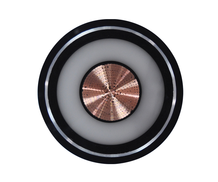
Moving into medium voltage requires a transition from simple insulation to complex cable construction. MV cables incorporate conductor shields, insulation shields, and metallic screens to manage electrical stress evenly across the dielectric material. The conductor shield smooths out the electrical field, preventing high-stress points around the individual wire strands. The insulation shield confines the electrical field within the dielectric. Utility distribution networks, large motor feeders, and renewable energy collector systems rely heavily on MV cables. The decision process here involves precise calculations of fault currents to size the metallic shield (tape or wire) appropriately so it can carry the ground fault current back to the source without melting.
Transmission-level requirements dominate the HV and EHV tiers. These cables transport massive amounts of power over long distances. They demand custom engineering, specialized dielectric testing, and stringent manufacturing tolerances. Minor impurities in the XLPE insulation at 110kV or 220kV cause rapid partial discharge and failure. Manufacturing requires continuous vulcanization (CCV) lines and extensive degassing periods to remove methane and other byproducts of the cross-linking process. Specification at this level requires direct collaboration with manufacturers to ensure the cable meets the exact parameters of the utility grid, including custom sheath bonding configurations (single-point, cross-bonded) to eliminate circulating currents.
The 100% insulation level applies to solidly earthed systems where ground faults clear rapidly. Industry standards dictate that the protection relays and breakers must isolate the fault within one minute. Because the phase-to-ground voltage does not remain elevated for long, standard insulation thickness suffices. In simplified industry terminology, "100% level" equates directly with "earthed" systems. This is the most common specification for standard commercial and light industrial distribution networks where rapid trip times are guaranteed by well-coordinated protective relays.
Unearthed or impedance-grounded systems require a 133% insulation level. In these architectures, ground faults may persist for up to one hour before the system clears them. During this time, the voltage on the unfaulted phases rises to the phase-to-phase voltage. The cable requires increased insulation thickness to handle this sustained phase-to-ground voltage stress without breaking down. Heavy industrial facilities, such as refineries and paper mills, often utilize high-resistance grounding (HRG) to maintain operations during a single ground fault, making 133% insulation mandatory.
Certain critical industrial processes cannot shut down immediately during a ground fault. These systems must continue operating indefinitely until a safe shutdown is possible. This scenario demands a 173% insulation level. The cable features the highest level of dielectric strength to withstand continuous, elevated voltage stress across the unfaulted phases. Marine applications, offshore drilling rigs, and continuous chemical processing plants frequently specify 173% insulation to prevent catastrophic process interruptions.
| Insulation Level | System Grounding Type | Maximum Fault Clearing Time | Application Scenario |
|---|---|---|---|
| 100% | Solidly Earthed | < 1 Minute | Standard utility distribution, rapid trip commercial systems. |
| 133% | Unearthed / Impedance | < 1 Hour | Industrial plants requiring orderly shutdown, HRG systems. |
| 173% | Resonant / High Impedance | Indefinite | Critical continuous processes, marine and offshore applications. |
Operating temperatures directly impact dielectric strength. As a cable heats up from current flow or ambient conditions, the insulation softens and its electrical resistance drops. You must evaluate the interplay between voltage rating, conductor sizing, and ambient temperature derating factors using established methods like the Neher-McGrath calculations. Pushing maximum ampacity through a cable in a high-temperature environment degrades the insulation, effectively lowering its safe voltage threshold over time. Underground duct banks require careful thermal modeling to ensure the inner cables do not exceed their 90°C or 105°C continuous operating limits.
Environmental realities dictate the outer layers of the cable. Direct burial, submerged applications, and petrochemical exposure necessitate specific jacketing materials like XLPE, EPR, or CPE. These outer sheaths provide essential physical barriers. They defend the underlying voltage-rated insulation from moisture treeing, chemical degradation, and mechanical impacts during installation. For rocky terrain or industrial trays subject to physical impact, interlocked aluminum armor or continuously welded corrugated aluminum sheathing provides the necessary mechanical defense. If the jacket breaches, water ingress will inevitably compromise the voltage rating.
Fire safety categories intersect heavily with voltage ratings in commercial and confined-space industrial environments. General-purpose (CM/CMG), riser (CMR), plenum (CMP), and Low Smoke Zero Halogen (LSZH) designations dictate where a cable can run safely. A 15kV MV cable routed through an underground transit system requires both the correct dielectric strength and strict LSZH compliance to prevent toxic smoke during a fire event. Specifying the wrong fire rating leads to immediate failed inspections and costly rework, regardless of whether the electrical voltage rating is correct.
Solar PV installations, Battery Energy Storage Systems (BESS), and EV charging infrastructure operate on direct current. DC system voltage (Vdc) requires distinct cable ratings compared to AC RMS voltages. AC voltage fluctuates, crossing zero, which gives insulation brief moments of relief. DC voltage applies continuous, unyielding stress, leading to space charge accumulation within the dielectric material. This trapped charge distorts the internal electrical field. You must calculate the exact current load, including peak currents, when sizing DC cables to prevent thermal breakdown of the insulation. Standard AC cables cannot be arbitrarily repurposed for high-voltage DC applications without verifying the manufacturer's DC rating.
Power electronics introduce severe stress. High-frequency switching and harmonics from inverters create aggressive voltage spikes. These spikes attack cable insulation, accelerating aging and leading to premature failure. Systems utilizing Variable Frequency Drives (VFDs) or large solar inverters often require higher voltage ratings or specialized VFD cables with enhanced shielding and thicker dielectrics to contain the high-frequency noise and withstand the voltage peaks. The reflected wave phenomenon in long VFD cable runs can double the voltage at the motor terminals, destroying standard insulation rapidly.
| Stress Factor | AC Cable Systems | DC Cable Systems |
|---|---|---|
| Voltage Profile | Alternating, crosses zero, provides dielectric relief. | Continuous stress, no zero-crossing relief. |
| Dielectric Challenge | Capacitive charging currents, partial discharge. | Space charge accumulation, field distortion. |
| Harmonic Impact | Standard grid harmonics, manageable with standard shielding. | Severe high-frequency switching spikes from inverters. |
Choosing a higher-than-necessary cable voltage rating introduces significant physical and financial trade-offs. A 15kV cable used on a 4.16kV system provides a massive safety margin but drastically increases the outer diameter (OD). This larger OD reduces cable flexibility, increases the minimum bend radius, and forces the use of larger conduits and cable trays. The structural support costs escalate quickly. Pulling tensions increase, requiring heavier equipment and increasing the risk of damaging the cable during installation. Over-specification wastes capital on copper, insulation, and support infrastructure without providing tangible operational benefits.
Mismatched components create severe implementation risks. Splices, terminations, and lugs must be explicitly rated for the chosen cable voltage and insulation thickness. Trying to fit a 15kV termination kit onto a 5kV cable, or vice versa, leads to improper stress cone formation. The stress cone is critical; it manages the electrical field at the point where the insulation shield is cut back. Misalignment causes localized electrical stress concentrations, resulting in rapid tracking, partial discharge, and explosive termination failure. Installers must meticulously measure the insulation diameter after removing the semiconducting layer to ensure the termination body fits perfectly.
Engineers often confuse voltage rating with voltage drop. Voltage rating defines the insulation capacity, while voltage drop relates to conductor resistance over distance. A higher voltage rating does not fix voltage drop. To prevent excessive voltage drop, you must size the copper or aluminum conductors appropriately. Use calculation spreadsheets, sizing software, and manufacturer tools to ensure the voltage at the load remains within acceptable equipment tolerances. Increasing the conductor size lowers resistance, but it also increases the overall cable weight and diameter, requiring a recalculation of conduit fill and pulling tensions.
A: The insulation will experience excessive electrical stress, leading to rapid dielectric breakdown. This causes short circuits, equipment damage, potential fires, and immediate system failure.
A: Yes. Using a 1000V cable on a 400V or 480V system is common in industrial environments. It provides a thicker insulation barrier, offering better resistance to mechanical damage and minor electrical transients.
A: The 100% level is for systems that clear ground faults within one minute. The 133% level features thicker insulation for systems that may sustain ground faults for up to one hour before clearing.
A: Proper jacketing protects the internal insulation from moisture, chemicals, and mechanical impacts. If the outer jacket fails, environmental factors will degrade the dielectric material, causing the voltage rating to drop and the cable to fail.
A: Yes. DC voltage applies continuous stress without the zero-crossing relief found in AC systems. Cables must be specifically rated for DC applications to handle this constant dielectric strain and potential inverter harmonics.
A: Um is defined by international standards based on the nominal grid voltage. It represents the highest continuous RMS voltage the system can experience under normal operating conditions, usually 5% to 10% above nominal.
A: No. Voltage rating dictates insulation strength, not conductivity. To reduce voltage drop, you must increase the cross-sectional area of the conductor (wire gauge) to lower its electrical resistance.
 简体中文
简体中文 

