

Views: 0 Author: Site Editor Publish Time: 2026-08-20 Origin: Site


Failing underground electrical installations demand expensive excavation, cause operational downtime, and pose severe safety hazards. Selecting the correct Underground Power Cable requires balancing soil conditions, mitigating voltage drop over long distances, classifying by specific voltage needs, and adhering to strict local electrical codes. It is never just about matching ampacity to a breaker. You must evaluate direct burial versus conduit systems, sizing requirements, and insulation types to ensure long-term reliability and compliance. A poorly specified cable buried three feet deep becomes a massive liability the moment the ground freezes or shifts. We will break down the exact technical requirements, environmental assessments, and installation methods necessary to execute a flawless underground electrical routing project.
Calculating total amperage needs establishes the baseline for any electrical routing project. You must classify the project by voltage tier early in the planning phase. Low voltage residential applications typically operate at 120V or 240V. Medium and high voltage industrial grid applications require entirely different cable construction types. Distance dictates the baseline for acceptable voltage drop parameters. Long underground runs inherently suffer from voltage drop, which forces engineers to upsize conductors to maintain efficiency. When you run a circuit past 100 feet, the natural resistance of the copper or aluminum wire begins to choke the voltage. If you start with 240V at the main panel, you might only deliver 220V at the subpanel if the wire is undersized. This voltage drop forces motors to work harder, pull more current, and eventually burn out prematurely.
To prevent this, you must calculate the exact load in amps and the total one-way distance of the run. Standard practice dictates keeping voltage drop below 3% for branch circuits and 5% for overall feeders. If your calculation shows a 6% drop, you must step up to the next wire gauge. For example, a 20-amp circuit running 150 feet might require 10 AWG wire instead of the standard 12 AWG. Always factor in future capacity. If you are trenching 200 feet to a detached garage, size the wire for a 100-amp subpanel even if you only need 60 amps today. The labor to dig the trench remains the same, but pulling larger wire now prevents a complete redo later.
Site-specific environmental factors dictate cable survival. You must assess water tables, continuous moisture exposure, and soil acidity or alkalinity before trenching. High soil acidity degrades standard jackets rapidly. Mechanical threats also dictate cable durability requirements. Frost heave, rocky terrain, and potential rodent damage require robust physical defenses. Standard insulation fails quickly when subjected to sharp rocks during backfilling or shifting ground conditions. Soil composition plays a massive role in thermal dissipation. Sandy soils drain well but hold heat, which can lower the ampacity rating of the buried cables. Clay soils retain moisture, providing better thermal conductivity but increasing the risk of frost heave in colder climates.
You must also evaluate the frost line in your specific region. Burying cables above the frost line subjects them to aggressive freeze-thaw cycles. The ground expands and contracts, putting immense physical strain on the cable jacket and any conduit joints. If you are trenching in areas with high water tables, assume the conduit will eventually fill with water. This reality makes wet-rated insulation non-negotiable. Furthermore, areas with heavy agricultural runoff often contain fertilizers and chemicals that alter soil pH. Highly acidic or alkaline soils will attack standard PVC jackets over time, requiring specialized chemical-resistant sheathing or concrete encasement for long-term survival.
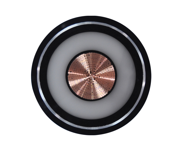
A buried power cable designed for direct earth contact eliminates the need for external piping. UF-B (Underground Feeder) typically serves branch circuits, while USE-2 (Underground Service Entrance) handles main power feeds. Direct burial offers lower initial material requirements and faster trenching processes in ideal, non-rocky soils. However, these cables remain vulnerable to physical damage from future digging. Upgrading the wire later is impossible without executing a full re-trenching operation. UF-B features a solid plastic jacket that encapsulates each conductor individually, making it highly resistant to moisture but incredibly stiff and difficult to bend in tight spaces.
USE-2 cable is built for harsher conditions. It utilizes a cross-linked polyethylene insulation that withstands higher operating temperatures and rougher handling during installation. When installing direct burial cables, the trench bottom must be completely free of sharp rocks or debris. Standard practice involves laying a bed of clean sand, placing the cable, and covering it with another layer of sand before backfilling with native soil. This sand bedding prevents point-loading on the cable jacket when the earth settles. Despite these precautions, direct burial remains a one-way street. If a conductor fails or you need more power in five years, you have to dig up the entire yard again.
Pulling individual conductors through a buried conduit system provides structural advantages. THWN or THWN-2 wires inside PVC or rigid metal conduit offer maximum physical protection against soil shifting. This method ensures operational ease when pulling new or larger wire for future capacity upgrades. The primary drawbacks include higher upfront material requirements and increased labor hours necessary for conduit assembly, bending, and gluing. Schedule 40 PVC is the standard for underground residential and light commercial work, while Schedule 80 PVC is required where the conduit emerges from the ground and is subject to physical damage.
Rigid metal conduit (RMC) provides the ultimate physical protection and allows for the shallowest trench depths under the NEC. However, RMC requires specialized threading equipment and is highly susceptible to corrosion in acidic soils unless factory-coated with PVC. When assembling a PVC conduit system, you must use proper primer and solvent cement on every joint to prevent root intrusion and minimize water ingress. You also need to install expansion fittings on long runs to account for thermal expansion and contraction. The ground shifts, and temperature changes cause PVC to expand; without expansion joints, the conduit will snap, exposing the wires to the earth.
| Installation Method | Primary Use Case | Physical Protection | Future Upgradability |
|---|---|---|---|
| Direct Burial (UF-B/USE-2) | Simple residential runs, agricultural feeds | Low to Moderate | None (Requires re-trenching) |
| PVC Conduit (THWN) | Commercial, future-proofed residential | High | Excellent (Easy to pull new wire) |
| Rigid Metal Conduit | Heavy industrial, shallow trenching | Maximum | Excellent |
Moisture resistance and thermal performance depend entirely on insulation chemistry. XLPE (Cross-linked Polyethylene) outperforms PVC (Polyvinyl Chloride) in wet underground environments due to its superior thermal stability and moisture resistance. Portions of the cable transitioning above ground to a panel or meter demand UV-resistant jacketing. Sunlight degrades standard insulation rapidly, leading to cracking and eventual ground faults. XLPE insulation can handle operating temperatures up to 90 degrees Celsius in both wet and dry locations, making it the standard for heavy-duty underground service entrances.
PVC insulation, commonly found on THHN/THWN wires, is thinner and more flexible, which makes pulling it through conduit much easier. However, you must ensure the wire carries the "W" designation (like THWN), indicating it is rated for wet locations. Underground conduits will eventually accumulate condensation or leak, meaning the wires will sit in water. Using standard dry-rated wire underground guarantees a catastrophic insulation failure. Furthermore, any wire exposed to the sun at the service mast or exterior panel must be explicitly marked as sunlight resistant. UV rays break down the polymers in standard jackets, causing them to turn brittle and flake off within a few years.
Heavy industrial sites, high-traffic commercial areas, and zones prone to severe ground movement necessitate an armored underground cable. Armor provides a physical steel or aluminum barrier against crushing forces. Medium-to-high voltage applications rely on concentric neutral wires and metallic tape shields. These components manage electrical stress and provide a safe return path for fault currents, ensuring personnel safety and equipment protection. In medium voltage applications (typically above 2,000 volts), the electrical field surrounding the conductor becomes intense enough to break down the insulation if not properly managed.
The metallic shield confines the dielectric field within the cable, equalizes voltage stress across the insulation, and prevents surface discharges. When installing shielded cables, the termination process requires specialized stress cones and grounding kits. You cannot simply strip the wire and land it on a lug. The shield must be properly grounded at the terminations to carry fault currents back to the source and trip the overcurrent protection device. Armored cables, such as Teck 90 or MC-HL, combine this electrical shielding with a rugged interlocking metal armor and an overall PVC jacket, providing a self-contained, highly durable routing solution that often eliminates the need for rigid conduit entirely.
Systematically upsize conductors to keep voltage drop below the recommended 3% threshold. Utilize a standard underground wire size chart to match distance and load accurately. Copper conductors offer superior conductivity and smaller overall diameters. Aluminum conductors provide weight advantages but carry thermal expansion risks. You must apply anti-oxidant compounds on all aluminum terminations to prevent oxidation and high-resistance connections. Copper is the gold standard for branch circuits and smaller feeders due to its flexibility and reliable termination characteristics.
However, for long, high-amperage underground runs, copper becomes prohibitively heavy. Aluminum is the industry standard for large service feeders. Modern AA-8000 series aluminum alloy conductors are highly reliable, provided they are installed correctly. Aluminum expands and contracts more than copper under thermal load. This movement can loosen connections over time, leading to arcing and fires. You must use lugs specifically rated for aluminum (marked AL7CU or AL9CU), wire-brush the exposed aluminum strands to remove the invisible oxide layer, immediately apply a liberal coating of anti-oxidant paste, and torque the lugs to the manufacturer's exact specifications using a calibrated torque wrench.
Direct burial installations require fewer materials upfront compared to full conduit systems. However, you must weigh this against long-term maintenance risks. If a cheaper, non-conduit cable fails prematurely due to ground shifting or rodent damage, the physical risk of future excavation is substantial. Conduit systems mitigate this risk by isolating the conductors from direct soil contact. When a direct burial cable faults, locating the exact point of failure requires specialized underground fault-finding equipment. Once located, you have to dig up that section, splice the cable using an approved underground splice kit, and rebury it. These splices often become the weak point for future failures.
With a conduit system, if a wire fails or the insulation degrades, you simply pull the old wire out and pull new wire in. There is no digging required. This reliability factor makes conduit the preferred choice for any permanent structure or critical infrastructure. Furthermore, conduit allows you to leave a pull string inside the pipe for future use. If you anticipate needing a dedicated circuit for an electric vehicle charger or a heavy workshop tool in the future, installing an oversized conduit now saves massive amounts of labor later.
Trenching equipment rentals and labor hours scale directly with required depths. Digging a 24-inch trench demands significantly more time and heavier machinery than a 12-inch trench. Local terrain heavily impacts installation speed. Trenching through soft clay progresses rapidly, while excavating rocky terrain shatters project timelines and requires specialized rock-saw equipment. For short runs in clean soil, a walk-behind trencher handles the job efficiently. For deep trenches, rocky soil, or runs exceeding 100 feet, a mini-excavator becomes necessary.
You must also factor in the labor required for backfilling and compaction. Simply pushing the dirt back into the trench and walking away guarantees severe ground settling later, which creates tripping hazards and drainage issues. The trench must be backfilled in 6-inch lifts, with each lift mechanically compacted using a jumping jack or plate compactor. If you are installing PVC conduit, the labor involves measuring, cutting, deburring, and gluing hundreds of feet of pipe. The pipe must be laid as straight as possible; every 90-degree bend increases the pulling tension exponentially. The NEC strictly limits conduit runs to a maximum of 360 degrees of total bends between pull points to ensure the wire can actually be pulled through without tearing the insulation.
Standard NEC burial depths depend entirely on the installation method. Code generally requires 24 inches for direct burial, 18 inches for PVC conduit, and 6 inches for rigid metal conduit. Critical depth exceptions exist based on voltage and circuit type. The NEC allows a 12-inch trench depth for 120V, GFCI-protected residential circuits capped at 20 amps. 240V lines demand deeper trenches. Mitigate trenching risks by installing underground warning tape above the underground electrical cable. Bed the trench with sand rather than sharp native rocks to protect the jacket during backfill.
These depth requirements are measured from the top of the cable or conduit to the finished grade of the soil. If you are trenching under a driveway or parking lot, the rules change. Direct burial cables and PVC conduits typically must be buried at least 24 inches deep under areas subject to vehicular traffic to prevent the weight of the vehicles from crushing the installation. Rigid metal conduit can sometimes be buried shallower under concrete slabs, but you must always verify with local amendments. Installing red warning tape 12 inches above the buried electrical line is a critical safety step. When someone digs in the future, they will hit the warning tape before they strike the live high-voltage lines.
Contacting local utility locators before excavation is an absolute legal and safety requirement. Dialing 811 prevents lethal strikes on existing gas, water, or high-voltage infrastructure. Schedule municipal or utility inspections proactively. The trench must remain open and visible until the inspector physically signs off on the installation. Backfilling before inspection guarantees a failed permit and forced re-excavation. Utility locators will mark the ground with color-coded paint to indicate the presence of buried lines. Red indicates electrical, yellow indicates gas, and blue indicates water.
You must respect the tolerance zones around these markings, which typically require hand-digging only within 18 to 24 inches of the paint marks. Striking a buried gas line or a primary utility feeder is a catastrophic event that can result in severe injury, massive fines, and immediate project shutdown. Once the trench is dug and the conduit or cable is laid, you must call the local Authority Having Jurisdiction (AHJ) for a rough-in inspection. The inspector will verify the trench depth, the type of cable or conduit used, the presence of warning tape, and the proper use of expansion fittings. Only after the inspector signs the permit card are you legally allowed to begin the backfill process.
A: UF-B (Underground Feeder) is typically used for residential branch circuits and lighting. USE-2 (Underground Service Entrance) features thicker insulation, handles higher temperatures, and is designed for main power feeds connecting utility transformers to building meters.
A: Direct burial for a standard 240V circuit requires a 24-inch trench. A 120V residential circuit protected by a GFCI breaker and rated at 20 amps or less can legally be buried at a 12-inch depth.
A: No. Standard indoor wire like NM-B lacks the moisture-resistant insulation required for underground environments. Conduits buried in the earth will accumulate water, requiring wet-rated conductors like THWN or THWN-2.
A: Armored cables are required in environments with high risks of mechanical damage, such as heavy industrial sites, areas with severe ground shifting, or commercial zones where standard conduit cannot provide sufficient crush resistance.
A: Voltage drop is calculated using the conductor's resistance, the total distance of the run, and the anticipated load in amps. You must upsize the wire gauge if the calculated drop exceeds the recommended 3% threshold.
A: Direct burial wire is designed to be placed directly in the earth without conduit. However, code requires it to be sleeved in conduit where it emerges from the ground to protect it from physical damage.
 简体中文
简体中文 

