

Views: 0 Author: Site Editor Publish Time: 2026-08-18 Origin: Site


The power cable connecting a generator to a load acts as the most vulnerable point of failure in any temporary or backup power distribution system. Incorrect specification introduces severe risks, including drastic voltage drop, equipment damage due to under-voltage conditions, thermal overload, and non-compliance with National Electrical Code (NEC) or OSHA standards. Relying on undersized or improperly jacketed cords compromises the entire electrical infrastructure, leading to costly downtime and significant safety hazards on site.
Selecting the correct Generator Power Cable requires a systematic approach rather than guesswork. Evaluating load requirements, environmental conditions, material quality, and connection standards provides a precise framework to specify a reliable, code-compliant power delivery solution. This guide breaks down the technical parameters necessary to match your generator's output with the appropriate cabling infrastructure, ensuring safe and continuous operation under heavy loads.
Auditing the intended use case establishes the baseline requirements for any temporary power setup. A residential backup system feeding a manual transfer switch demands different cable specifications than a mobile construction site powering heavy machinery or an industrial facility running sensitive diagnostic equipment. Defining the operational scope involves identifying the maximum potential load, the physical routing environment, and the duration of deployment. These factors directly influence the required ampacity, insulation type, and physical durability of the cord.
To accurately define the operational scope, field technicians and site managers should follow a strict auditing process before procuring any cabling:
Electrical loads fluctuate, making the distinction between continuous power and surge power highly relevant. Running watts represent the steady-state power drawn by equipment during normal operation. Starting watts, or surge power, account for the brief, massive spike in energy required to start electric motors found in compressors, pumps, and large appliances. The cable must handle the maximum breaker output of the generator, accommodating these surge loads without exceeding the thermal limits of the conductors. Sizing a cable based solely on average running watts guarantees overheating during motor startup sequences.
Regulatory adherence establishes the foundation for safe power delivery. Cables must carry verifiable UL (Underwriters Laboratories) or ETL listings, confirming they have passed rigorous independent safety testing. Adherence to local NEC guidelines for temporary power distribution ensures the installation meets baseline safety standards for grounding, overcurrent protection, and physical routing. Sourcing materials from reputable manufacturers with verifiable warranties eliminates the severe risks associated with counterfeit products, which often utilize substandard insulation and undersized conductors that fail catastrophically under load.
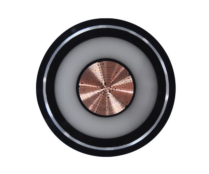
Wire thickness directly correlates to safe amperage capacity. The American Wire Gauge (AWG) system standardizes this relationship, with lower gauge numbers indicating thicker conductors capable of carrying higher currents. Undersizing the generator cable size forces excessive current through a restricted cross-sectional area. This creates high electrical resistance, generating dangerous levels of heat that melt insulation and trigger electrical fires. Proper sizing aligns the AWG rating with the generator's output breaker.
When working in the field, relying on a standardized matrix prevents dangerous under-specification. The following table outlines the minimum AWG requirements for standard copper conductors operating at standard ambient temperatures. Note that these are baseline figures; longer runs or high-heat environments require further up-sizing.
| Generator Breaker Size (Amps) | Minimum Copper Wire Gauge (AWG) | Typical Application |
|---|---|---|
| 20 Amps | 12 AWG | Small portable generators, power tools |
| 30 Amps | 10 AWG | Standard RV power, residential backup |
| 40 Amps | 8 AWG | Mid-sized commercial equipment, welders |
| 50 Amps | 6 AWG | Large RVs, whole-house manual transfer switches |
| 100 Amps | 2 AWG | Industrial temporary power distribution |
Budget cables frequently utilize Copper-Clad Aluminum (CCA) conductors to reduce manufacturing costs. CCA consists of an aluminum core coated with a thin layer of copper. Aluminum possesses significantly higher electrical resistance than pure copper. When subjected to heavy generator loads, CCA generates excessive heat and experiences severe voltage drop. To achieve the same ampacity as a pure copper cable, a CCA cable must be drastically upsized, making it bulky and difficult to manage on a job site.
For reliable generator power delivery, 100% pure bare copper or oxygen-free copper remains the strict industry standard. Pure copper offers superior conductivity, thermal stability, and mechanical flexibility. It withstands the repeated flexing and heavy current loads inherent in portable power applications without degrading or posing a fire hazard. Specifying pure copper conductors eliminates the hidden dangers associated with inferior CCA alternatives. Field inspections often reveal that melted plugs and scorched receptacles trace back directly to the high resistance of CCA wiring.
As electrical current travels through a conductor, inherent resistance causes a reduction in voltage, known as voltage drop. Acceptable voltage drop thresholds typically remain under 3% to 5% for optimal equipment performance. Exceeding this threshold starves connected equipment of voltage, causing motors to draw excessive current, overheat, and eventually burn out. Sensitive electronics may fail to operate entirely or sustain permanent damage.
Longer cable runs require stepping up to a thicker gauge to counteract increased resistance. A standard 10 AWG cable easily handles a 30-Amp load over 25 feet. However, pushing that same 30-Amp load over 100 feet necessitates upgrading to an 8 AWG cable to keep the voltage drop within safe limits. Calculating voltage drop involves factoring in the total amperage, the exact distance of the run, and the specific resistance of the chosen wire gauge. In commercial applications, engineers use the formula: Voltage Drop = (2 x Length x Resistance x Current) / 1000. Applying this formula ensures the voltage reaching the load remains within the safe operating window.
Mechanical trade-offs exist between rigid installation wire (like THHN or Romex) and portable power cords. Rigid wires belong inside conduit or permanent wall structures; they lack the physical durability to withstand external deployment. Portable generator applications demand a flexible generator cable designed to endure repeated coiling, uncoiling, dragging, and physical impact. Flexibility becomes mandatory in scenarios requiring frequent deployment, routing around obstacles, and cold-weather operations where standard PVC jackets become brittle and crack.
On active construction sites or during emergency disaster response, cables are constantly repositioned. A rigid cable will quickly develop internal micro-fractures in the copper strands, leading to localized hot spots and eventual failure. Flexible cables utilize finely stranded copper conductors rather than solid cores, allowing them to bend repeatedly without sustaining structural damage.
Industry-standard nomenclature dictates the physical properties of cord jackets. Understanding these letters ensures correct environmental matching. The National Electrical Code defines these designations to help users select the appropriate jacket for specific hazards.
Thermoset rubber (SOOW) provides exceptional durability, abrasion resistance, and flexibility across a wide temperature range, making it ideal for harsh industrial environments. Thermoplastic elastomer (SEOOW) offers similar flexibility and weather resistance but provides superior resistance to certain chemicals and remains lighter weight, suiting both demanding residential and commercial applications. Standard PVC (STW) lacks the extreme flexibility of rubber but serves adequately for basic, stationary outdoor use where physical impact is unlikely.
Jacket materials must withstand the specific environmental hazards of the deployment site. Prolonged exposure to UV radiation degrades inferior plastics, causing them to crack and expose live conductors. Ozone generated by electrical equipment or atmospheric conditions attacks rubber compounds. Industrial and construction sites expose cables to petrochemicals, oils, and harsh solvents. Selecting a jacket with dual oil resistance (the "OO" designation) and weather resistance (the "W" designation) guarantees the cable maintains its structural integrity and dielectric strength despite environmental abuse.
Power generation utilizes specific NEMA (National Electrical Manufacturers Association) configurations to ensure safe and standardized connections. Common configurations include the L14-30 (rated for 30A, 120/240V) and the L14-50 or CS6364 (rated for 50A). The "L" designates a locking plug. Twist-lock connectors provide a safety mechanism by physically locking the plug into the receptacle. This prevents accidental disconnections caused by vibration, tripping hazards, or the weight of the cable itself, maintaining a secure connection under heavy electrical load.
Using straight-blade connectors in high-vibration environments like generator enclosures often leads to the plug slowly backing out of the receptacle. This creates electrical arcing, which damages the prongs and poses a severe fire risk. Twist-lock configurations eliminate this risk entirely.
Connecting a portable generator to a building's electrical system requires a specialized generator connection cable linking the unit to a hardwired manual transfer switch or power inlet box. Powering standard 240V split-phase electrical panels mandates a 4-prong configuration. These four prongs consist of two hot wires (providing 120V each), one neutral wire, and one dedicated ground wire. This separation of ground and neutral ensures proper fault current paths and prevents the generator frame from becoming energized, strictly adhering to NEC safety protocols for backup power integration.
Mismatched receptacles occasionally require the use of adapters or "dogbone" cords. These short adapter cables safely bridge different NEMA configurations, provided they respect amperage limits. A strict safety rule dictates never stepping up amperage via an adapter without proper breaker protection. For example, plugging a 50A load into a 30A generator receptacle using an adapter forces the generator to supply more current than its breaker allows, leading to immediate breaker trips or potential overheating if the breaker fails. Adapters should only step down amperage or match configurations within the same ampacity rating.
Operating a generator with the power cable coiled creates a dangerous phenomenon known as inductive heating. The coiled wire acts as an electromagnet, concentrating heat and preventing the jacket from dissipating thermal energy into the surrounding air. This rapidly melts insulation and causes short circuits. Cords must be fully unrolled and laid flat before applying a load. Additionally, unbalanced loads on 240V split-phase systems force excessive return current onto the neutral wire. Distributing 120V loads evenly across both phases prevents neutral wire overload and maximizes generator efficiency.
Cables require physical protection from job site hazards. Routing paths must avoid vehicular traffic, sharp edges, and areas prone to standing water. When crossing walkways or roads, utilize heavy-duty polyurethane cable protectors to shield the jacket from crushing forces. Elevating cables using temporary hangers prevents submersion in mud or water and reduces tripping hazards. Implement strain relief devices at connection points to prevent the weight of the cable from pulling the plug out of the receptacle or damaging the internal wire terminations.
Proper storage extends the lifespan of expensive power cords. Coiling cables tightly around an elbow or using standard circular loops twists the internal conductors, leading to copper breakage and memory retention in the outer jacket. Utilize the "over-under" coiling method to lay the cable naturally without inducing internal torsion. Store cables in dry, climate-controlled environments away from direct sunlight. Prolonged UV exposure during storage accelerates the degradation of rubber and elastomer jackets, causing premature cracking and failure.
Choosing the correct generator cable remains a strict mathematical, material, and environmental calculation. Attempting to cut costs by undersizing the gauge, utilizing CCA conductors, or ignoring environmental jacket ratings guarantees equipment failure and introduces severe fire risks. A reliable power distribution system relies entirely on the integrity of its weakest link.
A: Using an undersized cable restricts current flow, creating high resistance. This causes severe voltage drop, starving connected equipment of power and potentially burning out electric motors. The excess resistance also generates extreme heat, which melts the cable insulation and creates a significant fire hazard.
A: CCA conductors have higher electrical resistance and lower ampacity than pure copper. They generate more heat under heavy loads, increasing the risk of melted insulation and electrical fires. Pure copper offers superior conductivity, flexibility, and safety for demanding generator applications.
A: Daisy-chaining cables is highly discouraged. Each connection point introduces additional electrical resistance, exacerbating voltage drop. Furthermore, standard plug connections are rarely waterproof, exposing the system to moisture intrusion and short circuits. Always use a single, continuous cable of the correct length.
A: A 3-prong cable typically supplies 120V power (one hot, one neutral, one ground). A 4-prong cable supplies 120/240V split-phase power (two hots, one neutral, one ground). The 4-prong configuration is mandatory for safely connecting to a home transfer switch to power 240V appliances.
A: Standard PVC jackets become rigid, brittle, and prone to cracking in sub-zero temperatures. Flexible cables utilizing thermoset rubber (SOOW) or thermoplastic elastomer (SEOOW) maintain their pliability in extreme cold, allowing for safe deployment, routing, and storage without damaging the outer jacket.
A: The length is theoretically unlimited, provided the wire gauge is proportionally upsized to counteract voltage drop. For example, a 30-Amp load might require 10 AWG for 25 feet, but 8 AWG or even 6 AWG for runs exceeding 100 feet to maintain safe voltage levels.
A: Yes, twist-lock plugs (NEMA L-series) are highly recommended for continuous power generation. They physically lock into the receptacle, preventing accidental disconnections caused by vibration, cable weight, or tripping, which ensures a secure and uninterrupted power supply under load.
 简体中文
简体中文 

