

Views: 0 Author: Site Editor Publish Time: 2026-08-15 Origin: Site


Direct current systems power sensitive telecommunications equipment, massive solar energy arrays, and industrial control panels. Unlike alternating current systems, DC power transmission is highly susceptible to severe voltage drop over distance. If you undersize the conductors, you risk system inefficiency and catastrophic thermal failures. Engineers and procurement teams face a complex balancing act. You must align strict electrical requirements—specifically amperage and voltage—with environmental durability, compliance standards, and operational constraints. Improper selection leads to immediate hardware damage or long-term safety hazards.
This guide provides a systematic evaluation framework for selecting the correct wiring for your specific application. We move from baseline electrical calculations and device label decoding to material selection and environmental risk mitigation. By understanding the physics of direct current and the properties of modern insulation, you can ensure reliable power delivery across any installation.
Before specifying any wiring, you must understand the foundational requirements of your equipment. Device labels and AC/DC power adapters provide the baseline data: Volts (V), Amperage (A), and Current Type. The voltage indicates the electrical pressure required by the device. The amperage denotes the volume of electrical current it draws under load. Identifying the solid line over a dashed line symbol confirms the requirement for direct current.
A fundamental rule governs this selection process. Always select a DC Power Cable with a higher amp rating than the device strictly requires. If a piece of equipment draws 5 amps continuously, utilizing a cable rated for 10 amps ensures the conductors stay cool under continuous load. This thermal headroom prevents insulation degradation and provides a buffer for unexpected power surges. When you look at a power supply rated for 24V and 15A, your wiring must handle that 15A peak without breaking a sweat. Field technicians often see melted barrel jacks because someone used a 5A rated wire on a 10A load. You must read the label, note the peak draw, and size up.
Voltage drop is the most significant physical constraint in direct current circuits. There is a strict linear relationship between cable length, conductor resistance, and the resulting voltage drop. As the distance between the power supply and the load increases, the natural resistance of the copper or aluminum conductor consumes a portion of the voltage. If the voltage drops too low, sensitive electronics malfunction, reboot, or fail to power on entirely.
Industry standards dictate acceptable voltage drop thresholds. For critical systems, engineer the circuit to maintain a voltage drop of 2% to 3%. For non-critical lighting or general loads, a 5% drop is acceptable. To maintain voltage integrity over specific distances, calculate the required cross-sectional area, measured in American Wire Gauge (AWG) or square millimeters (mm²). Proper DC cable sizing relies on formulas that factor in the total circuit length (both positive and negative runs), the peak current, and the specific resistance of the conductor material.
Consider a 12V system pushing 20 amps over 50 feet. The round trip is 100 feet of wire. If you use 10 AWG copper, the resistance is roughly 1 ohm per 1000 feet. That is 0.1 ohms for your run. Multiply 20 amps by 0.1 ohms, and you drop 2 volts. You just lost over 16% of your voltage. The equipment will fail. You would need to step up to 4 AWG or 2 AWG to keep that drop under 3%. This calculation is mandatory for every long run.
Ampacity defines the maximum amount of electrical current a conductor can carry continuously without exceeding its temperature rating. Continuous loads, defined as operating for three hours or more, require different calculations than intermittent peak loads. The minimum required cable thickness is directly dictated by these load profiles. Thicker cables possess a larger cross-sectional area, allowing them to carry more current and dissipate heat more effectively.
There is an intrinsic relationship between a cable's amp rating and its operating temperature. When determining the appropriate size, apply a safety margin. Standard engineering practice requires sizing the conductor for 125% of the continuous load. Furthermore, coordinate cable ampacity with system fuses or breakers. Standardizing on 15A rated cables for general commercial applications, rather than utilizing undersized 10A or 13A variants, prevents electrical bottlenecking. This ensures the overcurrent protection device trips before the cable overheats.
| AWG Size | Ampacity at 60°C (Amps) | Ampacity at 75°C (Amps) | Ampacity at 90°C (Amps) |
|---|---|---|---|
| 14 | 15 | 20 | 25 |
| 12 | 20 | 25 | 30 |
| 10 | 30 | 35 | 40 |
| 8 | 40 | 50 | 55 |
The choice of conductor material directly impacts performance, longevity, and project budget. Pure bare copper remains the industry standard due to its superior conductivity and flexibility. For marine environments, solar installations, or areas with high moisture, tinned copper is the superior choice. The tin coating provides excellent corrosion resistance, preventing the oxidation that degrades bare copper over time.
Aluminum offers a distinct set of advantages and drawbacks. It is significantly lighter, making it a common choice for large-scale utility projects and heavy feeder lines. However, aluminum is less conductive than copper. You must use larger diameter aluminum cables to match the ampacity of a smaller copper equivalent. Aluminum is prone to oxidation and requires specialized termination techniques, like applying anti-oxidant paste, to prevent high-resistance connections. Strand count matters heavily here. Solid core wire is suitable for fixed, rigid installations. High-strand count wire is mandatory for applications requiring flexibility and resistance to mechanical vibration.
When pulling wire through conduit, copper's smaller outer diameter for a given ampacity allows for easier pulls and better conduit fill ratios. If you switch to aluminum to save weight on a 200A feeder, you must upsize the conduit to accommodate the thicker wire. Always factor the conduit size into your material selection.
The conductor carries the current, but the insulation dictates where the cable safely operates. Different jacketing materials offer varying degrees of thermal, chemical, and mechanical protection. Selecting the wrong insulation guarantees premature failure.
| Insulation Material | Key Characteristics | Typical Temperature Ratings | Primary Applications |
|---|---|---|---|
| Polyvinyl Chloride (PVC) | Flexible, standard flame resistance. Vulnerable to extreme cold and prolonged UV exposure. | 60°C to 105°C | Standard indoor wiring, consumer electronics, controlled environments. |
| Cross-Linked Polyethylene (XLPE) | Excellent thermal stability, high moisture resistance, superior dielectric strength. Highly resistant to UV and abrasion. | 90°C to 125°C | Solar arrays, industrial power distribution, outdoor and direct burial. |
| Ethylene Propylene Rubber (EPR) | Exceptional flexibility, excellent weatherability, highly resistant to heat and oxidation. | 90°C to 105°C | Heavy industrial equipment, mining, applications requiring tight bending radii. |
Field conditions dictate the jacket. If you run wire across a factory floor where forklifts operate, standard PVC will crush and short out. You need a heavy-duty thermoset jacket like EPR. If you are wiring a rooftop solar array, the wire bakes in the sun all day. PVC will crack within a year. You must use XLPE rated for UV exposure.
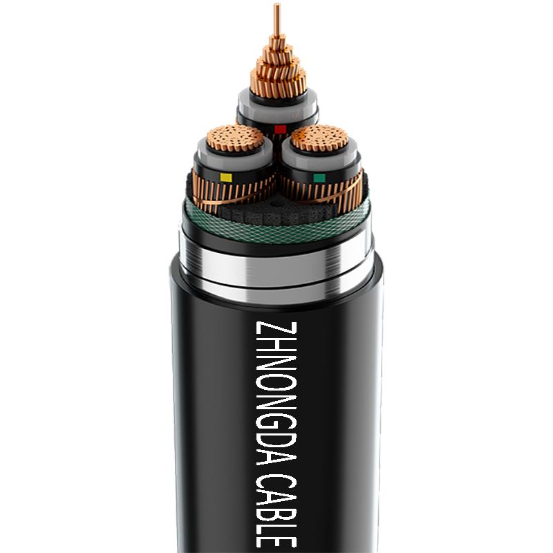
Operating environments impose severe stress on electrical infrastructure. Outdoor installations demand specific protective characteristics. A direct current cable deployed outside must feature UV resistance to prevent the jacket from becoming brittle and cracking under solar radiation. Moisture ingress protection is equally critical. Water penetration causes rapid oxidation and short circuits. If the routing requires underground placement, the jacket must be explicitly rated for direct burial to withstand soil acidity and mechanical pressure.
Industrial and automotive applications introduce chemical and mechanical threats. Cables in these environments require high oil resistance to prevent the insulation from swelling or dissolving. Abrasion resistance is necessary where cables drag across rough surfaces or experience continuous movement. Installations in freezing climates require specialized compounds that maintain flexibility in extreme cold, preventing the jacket from shattering during installation or operation.
Consider the depth of direct burial. Code requires specific depths depending on whether the wire is in conduit or directly in the dirt. Direct burial wire has a thicker, tougher jacket to resist rocks and shifting soil. Never bury standard indoor wire. The moisture in the soil will penetrate the jacket, corrode the copper, and create a ground fault.
Polarity is absolute in DC systems. Unlike AC circuits where current alternates direction, DC current flows strictly from positive to negative. Reversing this alignment instantly destroys sensitive capacitors and microcontrollers. Identify polarity symbols on power supplies. They typically show whether the center pin or the outer barrel is positive.
Standard color-coding conventions, such as Red for positive and Black for negative, help mitigate installation errors. Remain vigilant when dealing with non-standardized legacy systems where color codes may be arbitrary. Connector types vary widely based on the application. Barrel jacks are standard for AC/DC adapters. MC4 connectors dominate the solar industry. Anderson plugs handle high current loads in battery banks and material handling equipment. When replacing or selecting cables for electronics, matching the exact plug size—specifically the inner and outer diameter measurements—is critical. A loose connection creates electrical arcing and severe heat generation.
When assembling Anderson connectors, ensure the contacts are fully seated. A partially seated contact reduces the surface area for current transfer. This creates a high-resistance bottleneck. The connector will melt under heavy load. Always tug on the wire after inserting the contact into the housing to verify it is locked in place.
Procuring uncertified wiring introduces unacceptable liability and operational risk. You must select a DC electrical cable that carries appropriate regulatory certifications for your region. In North America, UL (Underwriters Laboratories) listing and NEC (National Electrical Code) compliance are mandatory for most commercial installations. For international deployments, IEC (International Electrotechnical Commission) standards govern performance and safety.
These certifications validate the manufacturer's claims regarding ampacity, maximum voltage rating, and insulation integrity. A UL-listed product undergoes rigorous third-party testing to ensure it will not degrade prematurely or pose a fire hazard when operated within its specified limits. Relying on certified products guarantees baseline quality and ensures compliance with local building and electrical inspectors.
Inspectors look for the print legend on the wire jacket. If they do not see the UL mark, the wire gauge, the temperature rating, and the voltage rating printed clearly on the jacket, they will fail the inspection. You will have to rip out the wire and pull new, certified wire. Do not risk it.
Fire safety ratings heavily influence procurement decisions, particularly for enclosed or high-occupancy spaces. Standard PVC insulation releases toxic, corrosive smoke when burned. For data centers, transit systems, and poorly ventilated areas, Low Smoke Zero Halogen (LSZH) cables are often required by code. LSZH materials emit minimal smoke and no toxic halogens during a fire, protecting personnel and preventing corrosive damage to nearby sensitive electronics.
Evaluate flame retardant ratings. The VW-1 (Vertical Wire) flame test is a common benchmark. Cables passing this test self-extinguish quickly when exposed to an open flame, preventing the fire from traveling along the cable tray or conduit. Matching the fire rating to the installation environment is a critical component of risk management. If you run wire through a drop ceiling used for return air, you must use plenum-rated wire. Plenum wire has a special jacket that resists burning and emits very little smoke.
Heat is the primary enemy of electrical insulation. A significant implementation risk arises when bundling multiple DC cables together. Bundled cables trap heat, raising the ambient temperature around the inner conductors. This trapped heat requires strict derating. You must artificially lower the ampacity rating of the cables to compensate for the reduced cooling capacity. Failure to derate bundled cables leads to thermal runaway, melted insulation, and electrical fires.
Mitigation strategies focus on airflow and spacing. Maintain proper physical spacing between high-current lines. Utilize open cable trays rather than enclosed conduits wherever possible to maximize natural convection cooling. Always adhere strictly to the manufacturer's derating charts based on both the number of bundled conductors and the ambient temperature of the installation environment.
If you run ten circuits through a single conduit, the NEC requires you to derate the ampacity of those wires to 50% of their normal rating. A wire normally rated for 20 amps can now only safely carry 10 amps. If you ignore this rule, the heat inside that conduit will build until the insulation melts and the wires short together.
The cable itself rarely fails. The failure almost always occurs at the termination point. Improper crimping or sloppy soldering introduces high-resistance points into the circuit. In a high-current DC system, this localized resistance generates extreme heat, eventually melting the connector and potentially igniting surrounding materials.
To mitigate termination failures, mandate the use of standardized, ratcheting crimping tools designed specifically for the terminals being applied. Avoid cheap, stamped tools that provide uneven pressure. For high-current connections, implement routine thermal imaging inspections. Scanning junction boxes and connector panels with an infrared camera allows maintenance teams to identify high-resistance hotspots and correct them before a catastrophic failure occurs.
When terminating fine-stranded wire into a screw terminal, always use a ferrule. If you just twist the bare strands and clamp them down, the screw will break some strands and push others aside. This reduces the effective wire gauge at the connection point. A ferrule gathers all the strands into a solid copper tube, ensuring a perfect, low-resistance connection.
Choosing the right wiring for a direct current system is a precise engineering decision governed by load requirements, transmission distance, and the operating environment. Ignoring the physics of voltage drop or the thermal limits of insulation guarantees system instability and introduces severe safety hazards.
A: While the physical copper conductor may be similar, DC cables require distinct insulation ratings and specific color-coding for strict polarity identification. DC systems are highly susceptible to voltage drop over distance, requiring stricter sizing protocols and thicker conductors compared to AC systems carrying similar power loads.
A: You must use a formula that incorporates the total current, the round-trip cable length, the acceptable voltage drop percentage, and the specific resistance of the conductor material. Professional voltage drop calculators simplify this process by outputting the required AWG or mm².
A: Read the adapter label to identify the exact voltage and confirm it outputs direct current. Ensure the new cable's amp rating exceeds the adapter's maximum output. Verify the physical plug size by measuring the inner and outer diameter, and confirm the polarity matches the device requirements.
A: Direct current flows in one direction. Reversing polarity can instantly destroy sensitive electronics, blow fuses, or cause fires. Clear color-coding and keyed connectors are essential features to prevent accidental reverse polarity during installation and maintenance.
A: No. Indoor cables typically use PVC insulation that degrades rapidly under UV exposure and extreme temperatures. Outdoor applications require UV-rated, moisture-resistant, and temperature-tolerant jacketing, such as XLPE, to prevent insulation cracking, water ingress, and subsequent short circuits.
A: An undersized cable creates excessive electrical resistance. This leads to a severe voltage drop, causing the connected equipment to malfunction or shut down. The resistance generates excessive heat, which can melt the insulation, expose bare wires, and trigger electrical fires.
A: The voltage rating indicates the maximum electrical pressure the cable's insulation can safely withstand without breaking down or allowing current to leak. The cable's voltage rating must always exceed the maximum operating voltage of the system it is installed in.
 简体中文
简体中文 

