

Views: 0 Author: Site Editor Publish Time: 2026-08-17 Origin: Site


Electrical wiring demands exact engineering and zero guesswork. Undersized conductors overheat, melt insulation, and start electrical fires. Oversized conductors waste project budget and fight you during tight conduit pulls. You must balance load requirements, continuous draw limits, voltage drop over long runs, and ambient heat. Selecting the exact wire gauge requires navigating a strict set of variables to keep the installation safe and operational.
This guide breaks down the exact methods to determine the right Power Cable Size for your specific installation. We cover the math, the code requirements, and the field realities of pulling wire. You will learn how to evaluate material trade-offs, apply regulatory standards, and handle specific use cases like residential branch circuits, heavy generator connections, and direct burial underground runs.
The American Wire Gauge (AWG) system dictates standard wire sizes in North America. The AWG scale works inversely. Higher numbers indicate smaller conductor diameters. A 12 AWG wire is physically smaller and carries less current than a 2 AWG wire. This inverse relationship trips up many apprentices, but it stems from the number of drawing operations required to manufacture the wire.
When cables exceed 1 AWG, the system transitions to the "aught" sizes. You must distinguish 0 AWG (written as 1/0 or one-aught) from larger sizes like 4/0 (four-aught). A 4/0 cable is significantly thicker than a 4 AWG cable. Mixing these up on a material takeoff ruins the installation timeline.
For heavy industrial and commercial applications, sizing shifts away from AWG entirely. We use MCM (thousand circular mils) or kcmil measurements. A 250 kcmil cable handles massive feeder loads that standard AWG sizes cannot touch. Understanding this progression is the first step in specifying materials.
| AWG / kcmil Size | Circular Mils (cmil) | Typical Application |
|---|---|---|
| 14 AWG | 4,107 | Standard lighting circuits |
| 12 AWG | 6,530 | Standard receptacle circuits |
| 10 AWG | 10,380 | Water heaters, small AC units |
| 4 AWG | 41,740 | Subpanels, large ranges |
| 1/0 AWG | 105,500 | Main service feeders (small) |
| 4/0 AWG | 211,600 | Main service feeders (standard) |
| 250 kcmil | 250,000 | Heavy industrial feeders |
Calculating the total electrical load dictates your baseline wire size. You find the required amperage by dividing total Watts by Volts. If you have a 4,800-watt heater running on a 240-volt circuit, it draws exactly 20 amps. However, you cannot just slap a 20-amp wire on a 20-amp load and walk away.
You must differentiate between continuous loads and non-continuous loads. A continuous load operates for three or more hours without stopping. Think of commercial lighting, EV chargers, or heavy HVAC equipment. The NEC mandates an 80% rule for these situations. A circuit breaker and its connected wire should only be loaded to 80% of their maximum rating for continuous use.
If that 4,800-watt heater runs continuously, the 20-amp draw represents 80% of the required circuit capacity. You divide 20 amps by 0.8 to get 25 amps. You must size the wire and the breaker for at least 25 amps. Failing to apply this math results in nuisance tripping and degraded insulation over time.
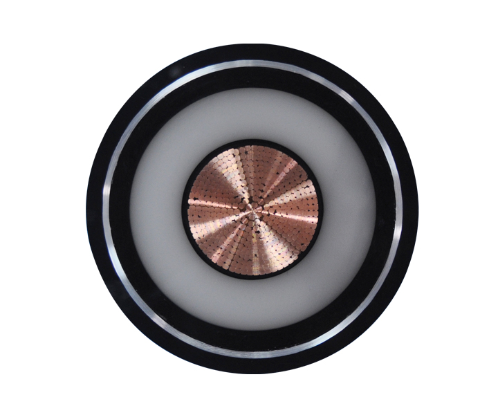
Calculate the total amperage required by the circuit or equipment. Check the nameplate data on the machinery. Look for the Full Load Amps (FLA) or Maximum Circuit Ampacity (MCA). This baseline measurement dictates the absolute minimum capacity the conductor must handle safely before any environmental adjustments.
Measure the exact physical distance from the power source to the load. Do not estimate straight lines through the air. Measure the actual path the conduit takes, including vertical drops, sweeps, and routing around structural beams. Accurate distance measurements prepare you for voltage drop adjustments. A 50-foot run behaves very differently than a 250-foot run under the same load.
Adjust your baseline ampacity requirements based on environmental conditions. Wires generate heat. If they cannot dissipate that heat, the insulation melts. You must apply derating factors in two main scenarios:
Cross-reference your adjusted amperage and distance requirements with an NEC-compliant ampacity chart. Look at the 75°C column for most standard terminations. Match your calculated load to the appropriate wire size. This finalizes the correct Power Cable Size for your project. Always round up to the next standard size if your math lands between two gauges.
Voltage drop occurs when electrical energy is lost as heat due to wire resistance over a distance. Pushing 20 amps through 200 feet of 12 AWG wire results in less voltage at the receptacle than at the breaker. Excessive voltage drop damages sensitive electronics, causes lights to flicker, and forces electric motors to pull more current, burning out their windings prematurely.
The industry standard requires maintaining a voltage drop of less than 3% for branch circuits and 5% for overall feeders. When run lengths increase, you must calculate distance adjustments. Often, you step up one or two wire gauges to maintain adequate voltage at the load. A 20-amp circuit running 150 feet usually requires 10 AWG wire instead of the standard 12 AWG.
| Variable | Definition | Field Application |
|---|---|---|
| VD | Voltage Drop | Target is <3% of source voltage. |
| K | Specific Resistance | 12.9 for Copper, 21.2 for Aluminum. |
| I | Current (Amps) | The actual load drawn by the equipment. |
| D | Distance (Feet) | One-way distance from source to load. |
| CM | Circular Mils | Cross-sectional area of the wire. |
Copper provides high conductivity and lower oxidation risk. It allows for a smaller conductor diameter for a given ampacity, making it ideal for tight conduits and complex routing. Copper bends easier and terminates cleaner. However, it is heavy and expensive.
Aluminum offers excellent weight reduction for heavy feeders. Pulling 250 kcmil aluminum is physically easier than pulling the copper equivalent. However, aluminum requires strict application of anti-oxidant compounds at every termination to prevent galvanic corrosion. You also need larger gauge sizes to match the ampacity of copper conductors. If a panel requires 3/0 copper, you might need 250 kcmil aluminum to carry the same load. This requires larger conduit, which changes your material list.
The bare metal carries the current, but the insulation dictates where you can install the wire. Insulation types map directly to specific environmental realities.
Ambient temperature derating factors force an increase in conductor size in hot environments to ensure the insulation does not melt or degrade. A wire rated for 90°C can handle more heat, but you must still size the circuit based on the weakest temperature rating in the system, which is usually the 75°C circuit breaker terminal.
Standard residential branch circuits follow rigid sizing rules. Inspectors look for these baselines immediately. A 14 AWG wire is typical for standard 15-amp lighting circuits. A 12 AWG wire supports 20-amp receptacle circuits in kitchens and bathrooms. For 30-amp heavy appliances like electric dryers or water heaters, a 10 AWG wire is required. Electric ranges usually demand 8 AWG or 6 AWG depending on their kilowatt rating. Never deviate from these minimums.
Connecting a backup power source involves unique requirements. You must handle peak starting wattage versus continuous running wattage. A compressor motor pulls a massive surge of current for a fraction of a second when it starts. Your wiring must handle that surge without dropping the voltage so low that the motor stalls.
When selecting a Generator Power Cable, evaluate the receptacle on the generator panel. You will typically choose between a 30-amp (L14-30) or a 50-amp (14-50) cord. Ensure twist-lock connector compatibility to prevent accidental disconnections during operation. Choose flexible SOOW or STOOW jackets for temporary outdoor use. These rubberized jackets resist oil, water, and UV degradation while remaining flexible in freezing temperatures.
Underground runs require direct burial cables like UF-B or individual THWN conductors inside PVC conduit. You must consult a dedicated underground wire size chart to accurately up-size for long runs to outbuildings. A 100-amp subpanel in a detached garage 150 feet away requires significantly larger wire than a 100-amp subpanel inside the main house.
For off-grid, mobile, or marine applications, low-voltage DC systems behave differently. Voltage drop occurs much faster in 12V or 24V DC systems than in 120V AC systems. Losing 2 volts on a 120V circuit is negligible. Losing 2 volts on a 12V circuit means your equipment stops working. Sizing logic differs significantly between heavy components like 3000-watt inverters (which might require massive 4/0 battery cables) and small DC loads like LED lighting (which can run on 14 AWG).
Verifying existing wire sizes requires a reliable method. Guessing leads to overloaded circuits and melted insulation. Follow these steps to identify unknown conductors in the field:
Ignoring terminal temperature ratings causes catastrophic failures. Many electricians look at the 90°C column in the ampacity chart and assume a 2 AWG copper wire can carry 130 amps. However, most circuit breakers and equipment terminals are only rated for 75°C. You must use the 75°C column, which limits that same 2 AWG wire to 115 amps. Pushing 130 amps through it will overheat the breaker terminals and cause a fire.
Failing to account for conduit fill limits leads to physical damage during pulling. Shoving nine 10 AWG wires into a 1/2-inch EMT conduit exceeds the fill capacity. The friction strips the insulation during the pull, causing immediate short circuits. Always default to the weakest link in the electrical circuit when finalizing your specifications.
A: Use the formula VD = (2 x K x I x D) / CM. Multiply 2 by the specific resistance (K), the current (I), and the distance (D). Divide that by the circular mils (CM) of the wire. Keep the result under 3% of your source voltage for branch circuits.
A: A 10,000-watt generator operating at 240 volts produces roughly 41.6 amps. You need a 6 AWG copper cable rated for 50 amps to handle the continuous load and starting surges safely.
A: Aluminum is used for large service feeders and subpanel feeds, not small residential branch circuits. If used, it requires larger gauges than copper and specific anti-oxidant treatments at every connection point.
A: The 80% rule states that a circuit breaker and its connected wiring should only be loaded to 80% of their maximum capacity if the electrical load operates continuously for three hours or more.
A: High ambient temperatures reduce a cable's ability to dissipate internal heat. You must apply temperature correction factors, which lowers the allowable ampacity and often forces you to select a larger wire gauge.
 简体中文
简体中文 

