

Views: 0 Author: Site Editor Publish Time: 2026-08-14 Origin: Site


While often treated as a commodity component, the internal architecture of a power transmission line dictates the safety, efficiency, and reliability of entire electrical systems. Specifying the wrong cable based on surface-level requirements rather than internal mechanical and electrical capabilities leads to thermal breakdown, voltage drop, compliance violations, and catastrophic operational downtime. In industrial and commercial environments, the physical realities of routing high-amperage circuits through conduits, trays, and underground ducts demand a rigorous understanding of conductor metallurgy and dielectric polymers. Ignoring the physics of electrical transmission, the material science behind cable construction, and the strict standards governing terminations guarantees premature failure. Evaluating technical specifications accurately ensures you select the correct cable for specific industrial, commercial, or specialized applications, preventing dangerous phase-to-phase shorts and maintaining continuous power delivery under maximum load conditions.
To evaluate a cable's suitability, engineers must first understand how it manages electrical energy and the physical byproducts of that transmission. A Power Cable operates as a dynamic environment where electrical and thermal forces constantly interact. Ignoring these physical realities during the specification phase guarantees premature failure. You cannot simply match an amperage rating to a breaker size and expect long-term reliability. The installation environment, continuous load profiles, and ambient temperatures all alter how the cable performs physically.
Electrical transmission relies on electron drift. Conductive metals facilitate efficient power transfer by providing a path of least resistance. The relationship between cross-sectional area and resistance is absolute. Larger conductors, measured in American Wire Gauge (AWG) or circular mils (kcmil), offer less resistance. This allows more current to flow without generating excessive heat. When you push current through a conductor, the inherent resistance of the metal creates friction at the atomic level, which manifests as heat.
Understanding conductor sizing requires referencing standard cross-sectional areas. The table below outlines common industrial sizes, their typical applications, and relative resistance profiles.
| Conductor Size | Cross-Sectional Area (mm²) | Typical Industrial Application | Relative Resistance Level |
|---|---|---|---|
| 12 AWG | 3.31 | Standard branch circuits, lighting | High |
| 8 AWG | 8.37 | Small motors, heavy equipment control | Moderate |
| 2 AWG | 33.6 | Sub-panels, medium machinery feeds | Low |
| 4/0 AWG | 107.2 | Main service entrances, large motors | Very Low |
| 500 kcmil | 253.4 | Heavy industrial distribution, switchgear | Extremely Low |
| 750 kcmil | 380.0 | Utility feeds, parallel generator runs | Minimal |
Voltage dictates the thickness and type of insulation required to prevent arcing. High voltage creates intense electrical fields that will breach weak dielectrics. Ampacity, or current-carrying capacity, generates heat. Thermal dissipation is a primary limiting factor in cable performance. If a cable cannot shed heat faster than it generates it, the insulation will melt, leading to a dead short.
Evaluating the thermal limits of a circuit requires a systematic approach on site. Follow these steps to ensure thermal dynamics remain within safe operating parameters:
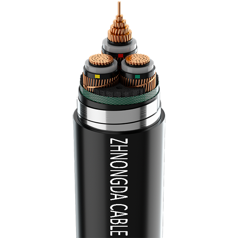
Breaking down the structural layers of a cable helps map physical features to operational outcomes. Every layer serves a distinct mechanical or electrical purpose. Missing or substandard layers compromise the entire assembly. Field engineers must inspect the cross-section of proposed cables to verify the presence and quality of each component.
Copper offers higher conductivity and requires a smaller cross-section for equivalent ampacity. It provides superior tensile strength but comes at a higher weight. Aluminum features lower weight and is highly practical for large-scale distribution networks. However, aluminum requires larger diameters and specialized termination techniques to prevent oxidation. Core configurations vary based on application. Single-core cables dominate high-voltage transmission. Multi-core assemblies bundled within a single sheath handle complex power distribution.
| Characteristic | Copper Conductors | Aluminum Conductors |
|---|---|---|
| Conductivity | Excellent (Standard reference) | Good (~61% of Copper) |
| Weight | Heavy | Lightweight (Easier to pull long distances) |
| Tensile Strength | High (Resists stretching during pulls) | Lower (Requires careful tension monitoring) |
| Termination Requirements | Standard mechanical or compression lugs | Requires oxide-inhibiting compound and specific dual-rated lugs (AL9CU) |
| Flexibility | High (Especially in fine-stranded variants) | Stiffer (Prone to metal fatigue if bent repeatedly) |
Insulation confines the electrical energy to the conductor. Thermoset materials like XLPE and EPR offer excellent thermal stability. They maintain integrity during overload conditions. Thermoplastic materials like PVC are flexible and easier to strip but melt under extreme heat. The choice of insulation directly impacts maximum operating temperatures and emergency overload capacities.
When selecting insulation, you must match the polymer to the environmental hazards of the site. XLPE (Cross-Linked Polyethylene) dominates industrial applications because the cross-linking process changes the molecular structure, preventing the plastic from melting even if conductor temperatures spike to 130°C during a short-term emergency overload. EPR (Ethylene Propylene Rubber) provides superior flexibility in cold weather and excellent resistance to corona discharge in medium voltage applications. PVC remains standard for indoor, climate-controlled commercial wiring due to its ease of installation and flame-retardant properties, but it becomes brittle in freezing temperatures and degrades rapidly under UV exposure.
Medium and high-voltage applications require shielding. Metallic shields, using copper tape or concentric wire, confine the dielectric field within the insulation. This prevents surface discharges that degrade the cable jacket. Shielding also provides a critical fault current return path, ensuring breaker operation during a short circuit.
In cables rated above 2,000 volts, the electrical field does not stay neatly inside the conductor. It pushes outward. Without a shield, this field interacts with grounded surfaces outside the cable, creating corona discharge—a localized ionization of air that produces ozone. Ozone rapidly destroys polymer jackets. A proper shielding system includes a semi-conducting layer over the conductor to smooth out voltage stress, the primary insulation, a second semi-conducting layer, and finally the metallic shield. You must ground this metallic shield at the terminations to drain off capacitive charging currents.
The outer jacket is the first line of defense against environmental degradation. Materials like CPE, Polyurethane, and Neoprene provide specific protections. You must evaluate these materials for UV resistance, moisture barriers, and flame retardancy based on the installation environment. A jacket failure inevitably leads to insulation failure once water or chemicals penetrate the core.
Cables interface with power sources and equipment via male plugs and female receptacles. Standard coupler configurations, such as IEC 60320 standards or NEMA ratings, ensure compatibility and secure connections. Factory-molded terminations offer superior protection against moisture ingress compared to field-wired alternatives. This is especially vital when deploying equipment in harsh environments.
Field terminations require strict adherence to manufacturer instructions. For medium voltage cables, the termination process is highly technical. You must strip the outer jacket, cut back the metallic shield to a specific dimension, and carefully remove the outer semi-conducting layer without scoring the primary insulation beneath it. Even a microscopic scratch on the XLPE insulation will cause localized voltage stress, leading to a tracking failure and an eventual blowout. Installers use specialized stress cones or heat-shrink tubes to manage the electrical field at the point where the shield ends.
Categorizing cables by voltage rating and environmental durability narrows down procurement options. You must match the physical build of the cable to the operational reality of the site. Over-specifying wastes budget, while under-specifying creates severe safety hazards.
Low voltage cables operate up to 1kV. This category includes standard building wire, control cables, and flexible cords. Medium voltage cables range from 1kV to 35kV. They serve distribution networks and require complex shielding and stress control layers. High voltage cables exceed 35kV. These form the backbone of transmission infrastructure and are heavily engineered to withstand extreme dielectric stress.
Low voltage systems rely primarily on the thickness of the insulation to contain the voltage. Medium voltage systems introduce the necessity of electrical field management. High voltage systems require specialized manufacturing environments, often utilizing pressurized nitrogen or oil-filled conduits to maintain dielectric integrity over long distances. You will rarely encounter high voltage cables inside a standard manufacturing facility; they terminate at the utility substation outside the fence.
Defining heavy duty requires looking at technical designations like SOOW or SEOOW, which indicate extra-hard usage ratings. A Heavy Duty Power Cable features reinforced thermoset jacketing and high stranding counts for maximum flexibility. Applications requiring these variants include mining operations, industrial manufacturing floors, marine environments, and temporary power distribution on construction sites.
When you specify a heavy duty variant, you are paying for mechanical survivability. Standard THHN wire pulled through a conduit is protected by the steel or PVC pipe. A heavy duty portable cord lies on the ground. It gets run over by forklifts, dragged across concrete, and submerged in puddles of cutting fluid. The stranding inside these cables uses hundreds of hair-thin copper wires (Class K or Class M stranding) rather than the 7 or 19 thicker strands found in stationary building wire. This fine stranding prevents the copper from work-hardening and snapping when the cable is repeatedly coiled and uncoiled.
Procurement must evaluate upfront material capabilities against operational demands. Selecting cables based purely on initial availability often results in undersized conductors or inadequate jacket materials that fail under site conditions. You must analyze the physical route the cable will take and the specific loads it will carry.
You must size cables not just for ampacity, but for acceptable voltage drop over long distances. Excessive voltage drop forces end-point equipment to draw more current, leading to motor burnout and equipment failure. Calculations must account for conductor resistance, load current, and total run length.
To calculate and mitigate voltage drop in the field, follow this procedure:
Assess flexibility requirements by looking at solid versus stranded conductors and the specific class of stranding. Installation environments dictate the necessary resistance to oils, solvents, abrasion, and crush forces. Direct burial applications require different mechanical protections than cables run in overhead trays.
Direct burial cables face constant threat from shifting soil, rocks, and rodent damage. These cables often incorporate steel tape armor or concentric neutral wires wrapped around the inner jacket to provide mechanical crush resistance. Cables installed in overhead cable trays must pass strict flame propagation tests (like the UL 1685 vertical tray flame test) to ensure a localized fire does not use the cable jacket as a fuel source to spread throughout the facility.
Validate manufacturer testing protocols before procurement. Essential tests include dielectric withstand testing (hipot), continuity checks, and insulation resistance testing. Rigorous manufacturing QA prevents premature failure and ensures the cable meets specified ampacity and voltage ratings out of the box.
Do not accept cables without factory test reports for medium and high voltage applications. A factory Very Low Frequency (VLF) test or a partial discharge test verifies that the insulation was extruded without microscopic voids or contaminants. A void in the XLPE insulation acts as a tiny pocket of gas. Under high voltage, this gas ionizes, creating partial discharge that slowly eats away at the surrounding polymer until the cable faults.
Navigate certifications carefully. Underwriters Laboratories (UL), National Electrical Code (NEC) ratings, and International Electrotechnical Commission (IEC) standards dictate safe installation parameters. Utilizing non-compliant or counterfeit cabling introduces severe safety hazards and liability risks.
Inspect the print legend stamped on the outer jacket of the cable. This legend contains the regulatory DNA of the product. It will list the manufacturer, conductor size, voltage rating, insulation type, and specific UL or CSA file numbers. If an inspector finds a cable lacking the proper listing marks for the specific application—such as using a non-plenum rated cable in a drop ceiling used for return air—they will force you to rip it out and replace it entirely.
Even perfectly specified cables fail if installed incorrectly. Common failure points occur during the physical pulling process and during operational load changes. The transition from a spool to a conduit is the most dangerous time in a cable's lifespan.
Operating cables in high ambient temperatures or bundled configurations without adjusting ampacity limits causes thermal overload. Apply NEC derating formulas based on conduit fill and environmental conditions. Failure to derate leads to insulation melting and phase-to-phase shorts.
When you bundle multiple current-carrying conductors in a single conduit, they heat each other up. The inner cables cannot dissipate heat to the surrounding air. You must apply adjustment factors to the baseline ampacity.
| Number of Current-Carrying Conductors | Ampacity Adjustment Factor (Multiplier) |
|---|---|
| 1 to 3 | 1.00 (No derating required) |
| 4 to 6 | 0.80 (80% of baseline ampacity) |
| 7 to 9 | 0.70 (70% of baseline ampacity) |
| 10 to 20 | 0.50 (50% of baseline ampacity) |
| 21 to 30 | 0.45 (45% of baseline ampacity) |
Exceeding maximum pulling tension or minimum bend radius causes invisible micro-tears in the insulation or snaps the conductor. Utilize proper lubrication during pulls. Calculate tension limits prior to installation. Always adhere to manufacturer bend radius specifications to maintain dielectric integrity.
Pulling a heavy cable through a 90-degree conduit sweep requires massive force. If you attach the pulling rope only to the outer jacket, the jacket will stretch and tear. You must use a pulling eye attached directly to the copper or aluminum conductors. Furthermore, bending a cable too sharply crushes the insulation on the inside of the bend and stretches it dangerously thin on the outside. For standard unshielded power cables, the minimum bend radius is typically 8 times the overall diameter of the cable. For shielded medium voltage cables, it increases to 12 times the diameter. Violating these limits voids the warranty and guarantees a future fault.
A power cable is not a static piece of metal and plastic, but a highly engineered system designed to balance electrical transmission with thermal and environmental realities. Procurement decisions must be driven by a sequential evaluation of required ampacity, voltage rating, environmental hazards, termination standards, and strict regulatory compliance.
A: Power cables transmit high-energy electrical currents to operate machinery and infrastructure. They feature larger conductors and thicker insulation to handle high voltages and thermal loads. Control cables transmit low-voltage signals to regulate equipment operations. They use smaller conductors and prioritize shielding to prevent electromagnetic interference from disrupting sensitive data.
A: Heavy duty variants feature thicker, reinforced thermoset jacketing designed to withstand severe mechanical abuse. They utilize higher stranding counts for extreme flexibility and continuous movement. The outer sheathing is engineered to resist industrial chemicals, oil, UV exposure, and severe abrasion, unlike standard PVC commercial wiring.
A: Shielding manages the dielectric field within medium and high-voltage cables. It evenly distributes electrical stress across the insulation, preventing localized breakdown. Shielding also provides a safe return path for fault currents, protects personnel from electrical shock, and mitigates electromagnetic interference with nearby equipment.
A: Failure typically stems from thermal degradation due to continuous overloading. Insulation breakdown occurs from moisture ingress, chemical exposure, or prolonged UV damage. Mechanical damage during installation, such as exceeding bend radius limits, creates weak points. Poorly executed terminations also cause high-resistance connections that overheat and fail.
A: Sizing requires calculating the continuous load ampacity of the connected equipment. You must then apply derating factors for high ambient temperatures and conduit fill limits. Finally, calculate the voltage drop over the total run length to ensure the conductor is large enough to deliver adequate voltage to the end device.
A: Cross-Linked Polyethylene (XLPE) is a thermoset plastic offering superior moisture resistance and excellent dielectric properties. It allows cables to operate at higher continuous temperatures (typically 90°C) and withstand higher emergency overload temperatures compared to standard thermoplastic PVC insulation, extending the cable's operational lifespan.
A: Common connectors include standard plug and receptacle pairings tailored to regional standards. North America relies on NEMA configurations for specific voltage and amperage ratings. Internationally, IEC 60320 couplers, such as C13 and C14, are standard for IT infrastructure and industrial equipment, ensuring secure and standardized power delivery.
 简体中文
简体中文 

