

Views: 0 Author: Site Editor Publish Time: 2026-08-15 Origin: Site


Blind excavation is one of the most dangerous gambles a construction crew can make. Striking an underground power cable leads to catastrophic safety incidents, immediate project shutdowns, and massive financial liabilities associated with utility strikes. Outdated utility maps, undocumented private lines, and shifting terrain make assumptions about buried utilities dangerous. An underground power cable is an invisible hazard that requires precise, verifiable detection before breaking ground.
Moving from guesswork to a systematic, technology-driven approach for utility locating is mandatory. This requires setting up a framework to evaluate equipment, methodologies, and operational protocols. We must abandon assumptions and rely on hard data, active signal tracing, and physical verification to ensure site safety and project continuity. Relying on outdated as-built drawings or surface markers alone is a recipe for disaster on any modern job site.
Breaching a high-voltage line poses immediate life-safety risks to equipment operators and ground crews. The sudden release of energy causes severe burns, electrocution, and arc flash explosions. Ground workers are particularly vulnerable to step potential. When a machine strikes a live line, electrical current travels through the soil, radiating outward from the strike point. A worker simply walking nearby can bridge two different voltage potentials with their feet, sending lethal current through their body. Touch potential is equally dangerous; anyone touching the excavator or nearby conductive materials when the strike occurs becomes a path to ground.
Heavy machinery operators often believe they are safe inside the cab due to the equipment's rubber tires or tracks. However, if they attempt to exit the machine after a strike without following proper jump-clear procedures, they risk completing the circuit to the ground. The physical force of an arc flash can also vaporize metal instantly, sending shrapnel and molten debris across the site.
A utility strike triggers a cascade of costs that quickly erode project margins. Contractors face direct utility repair bills, which can be astronomical for high-voltage transmission lines. Regulatory agencies levy heavy fines for safety violations and failure to follow safe digging protocols. Insurance premiums skyrocket following a strike, assuming the policy isn't canceled outright.
Beyond direct costs, contractors face severe legal liabilities. If a strike causes widespread outages, local businesses, hospitals, and industrial facilities may pursue litigation for lost revenue and operational disruptions. The financial burden of damaging an underground power cable often exceeds the profit margin of the entire project, sometimes bankrupting smaller contracting firms.
Utility strikes mandate immediate work stoppages. OSHA or equivalent health and safety agencies will launch thorough investigations, halting site progress until clearance is granted. The site becomes a restricted incident zone. These delays cause missed contractual deadlines, resulting in liquidated damages and strained client relationships.
Compliance failures also damage a contractor's reputation. Municipalities and large developers track safety records closely. A history of utility strikes can disqualify a company from bidding on future projects. Maintaining strict locating protocols is not just about safety; it is a core requirement for remaining competitive and eligible for major contracts.
Industry standards typically place electrical and water lines at a depth of 24 to 36 inches. However, telecom and cable lines are often buried at 12 inches or less. This creates a high risk of shallow utility strikes or signal confusion before operators even reach the depth of the power line. When sweeping a site, locators frequently pick up the stronger, shallower signals from telecom lines, masking the deeper, more dangerous electrical lines below them.
| Utility Type | Standard Expected Depth | Common Interference Issues |
|---|---|---|
| Telecom / Fiber Optic | 12 - 18 inches | High signal bleed; often masks deeper utilities. |
| Electrical (Secondary) | 24 inches | Subject to grading changes; often shares trenches. |
| Electrical (Primary/High Voltage) | 36+ inches | Deep burial weakens passive signals; requires active induction. |
| Water / Sewer | 36 - 48+ inches (below frost line) | PVC pipes require tracer wires or GPR for detection. |
Landscaping changes, erosion, and grading drastically alter the actual depth of an underground power cable. Previous unrecorded site work might have added or removed topsoil. A cable originally buried at 24 inches could now be sitting at 10 inches due to topsoil removal, or buried under three feet of fill dirt from a previous landscaping project. Never trust standard depth charts without physical verification.
Winter weather and frost heave also shift utilities over time. In colder climates, the freeze-thaw cycle pushes rocks and utilities upward. What was installed at a safe depth a decade ago may have migrated significantly closer to the surface.
Extremely rocky terrain makes standard trenching impossible. In these environments, contractors are forced into unpredictable routing or shallower-than-standard burial depths. Solid rock formations dictate the path of least resistance rather than a straight, predictable line. Installers might route a cable around a massive boulder or lay it shallow and cover it with concrete slurry, completely invalidating standard depth assumptions.
Cables laid directly in trenches emit signals differently than those protected by pre-made sections of concrete, concrete forms, or PVC conduits. Non-metallic conduits do not conduct locator signals well. If a tracer wire was not installed alongside the PVC conduit, or if the wire has corroded and broken, standard electromagnetic locators become useless. In these scenarios, ground penetrating radar or acoustic pipe locators become necessary to find the void or the conduit itself.
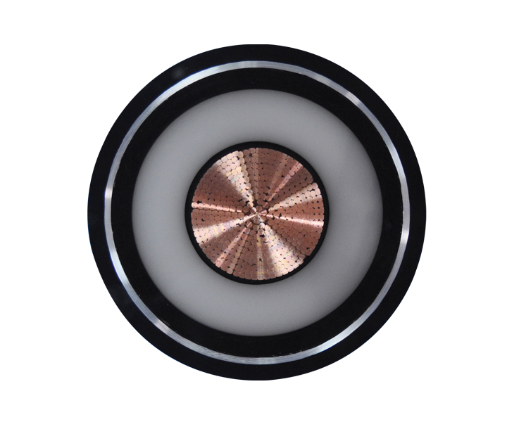
Passive locating detects the 50/60Hz electromagnetic field naturally emitted by live, loaded cables. It is a quick way to scan for energized lines during an initial site walk. Operators sweep the receiver across the ground, listening for the distinct hum of alternating current.
However, passive locating has severe limitations. It cannot detect dead or de-energized cables. If a facility is shut down or a specific circuit is turned off, the cable emits no field. Furthermore, well-shielded lines or balanced three-phase cables often cancel out their own electromagnetic fields, making them invisible to passive sweeps. Passive locating is also highly susceptible to interference from other nearby utilities carrying stray currents, leading to false positives.
Active locating uses a transmitter to apply a specific frequency to the target cable and a receiver to trace it. This is the industry standard for accurate utility mapping. There are three main ways to apply this active signal:
GPR is a complementary technology used when cables are housed in non-metallic conduits like PVC or fiberglass, or heavy concrete forms that do not conduct a locator's signal. GPR sends high-frequency radio waves into the ground and measures the reflected signals to detect changes in subsurface density. It creates a cross-sectional image of the ground, revealing trenches, pipes, and conduits.
GPR has strict environmental limitations. It performs poorly in high-moisture or dense clay soils, as the water and minerals absorb the radar waves before they can penetrate deeply. It is highly dependent on soil conditions and requires a skilled technician to interpret the complex radar radargrams accurately.
Modern electromagnetic locators offer a range of frequencies, typically from 512 Hz up to 200 kHz. Understanding frequency behavior is the difference between finding the target line and chasing a ghost signal.
Low frequencies (e.g., 512 Hz, 8 kHz) travel further along the cable and experience less bleed-off onto adjacent utilities. They require a direct connection to work effectively. High frequencies (e.g., 65 kHz, 200 kHz) jump gaps, overcome poor grounding, and induce easily through the soil. However, they bleed heavily onto nearby pipes, fences, and telecom lines. Operators must start with the lowest viable frequency to isolate the target line in congested areas, only moving to higher frequencies when the signal drops off.
Transmitter wattage impacts the ability to push a signal through deep or highly resistive soil. Standard transmitters range from 1 to 10 watts. When dealing with dry sand, frozen ground, or deep burial depths, a powerful 10-watt transmitter ensures the receiver can pick up a clear, distinguishable signal above the background noise. Proper grounding of the transmitter is just as important as wattage; a poor ground stake connection will cripple even the most powerful transmitter.
Modern receivers equipped with omnidirectional antennas and distortion filters help operators navigate congested urban environments. Older single-antenna models require the operator to hold the receiver at a specific angle to catch the signal. Multi-directional antennas allow for continuous tracking regardless of orientation.
Advanced software filters out "ghost signals" caused by adjacent utilities. These receivers display a distortion metric, alerting the operator when the magnetic field is no longer perfectly cylindrical. A distorted field indicates that the signal has bled onto another line or is bouncing off a nearby metallic structure, warning the operator not to trust the depth reading.
Analyze the return on investment of purchasing high-end electromagnetic locators and GPR carts versus the operational frequency of excavation projects. A top-tier EM locator and transmitter setup requires significant capital. GPR carts are even more expensive and require constant software updates and maintenance. If your crew only digs occasionally, the capital expenditure and maintenance costs of advanced equipment are not justified. Renting equipment or hiring contractors makes more financial sense for infrequent ground disturbance.
Interpreting locator signals and GPR data involves a steep learning curve. Equipment is only as accurate as the operator holding it. Inexperienced users easily misinterpret ghost signals, choose the wrong frequencies, or fail to identify deep lines, leading to false confidence and catastrophic strikes. Proper training requires weeks of field experience under the supervision of a master locator. Handing a locator to an untrained laborer is a massive liability.
Hiring third-party private utility locators transfers the liability of an unmarked private line strike away from the primary contractor. Specialized locating firms carry their own errors and omissions insurance. They bring a higher level of expertise, multiple types of equipment, and dedicated personnel to complex, congested sites. When digging in high-risk areas like hospitals, industrial plants, or dense urban centers, outsourcing the locating work is a standard risk-mitigation strategy.
A: The industry standard for electrical lines is typically 24 to 36 inches. However, terrain changes, rocky soil constraints, grading modifications, frost heave, and local codes drastically alter this depth. Never rely on standard depth charts; physical verification via potholing is always essential.
A: Yes, but passive locating will not work. You must use active locating by inducing a specific frequency signal onto the de-energized line using a transmitter. The receiver then traces this induced signal along the cable path.
A: Underground installation involves high trenching costs, difficult maintenance, and terrain limitations. Solid rock formations, high water tables, or dense urban infrastructure often make overhead lines more practical and cost-effective to install and repair.
A: Public utilities are owned by the service provider and typically end at the meter. Private lines run from the meter to other structures on the property (like detached garages or site lighting) and are not mapped or marked by standard 811 municipal services.
A: Accuracy degrades with depth, soil interference, poor grounding, and signal bleed from shallower lines like telecom cables. While locators provide a highly educated estimate of lateral position and depth, physical potholing is required for absolute certainty.
A: GPR detects changes in subsurface density. It finds the trench, the concrete form, or the conduit housing the cable, but it does not detect the electrical current itself. It is highly dependent on favorable soil conditions.
 简体中文
简体中文 

