

Views: 0 Author: Site Editor Publish Time: 2026-08-14 Origin: Site


The shift from overhead lines to underground infrastructure is accelerating rapidly. Utility operators and developers face mounting pressure to improve extreme weather resilience, meet urban density requirements, and modernize aging grids. Executing an electrical project with an Underground Power Cable requires heavy upfront capital expenditure. You also have to navigate complex geotechnical variables and avoid severe financial penalties tied to utility strikes or improper cable rating selection. Moving power delivery below the surface demands precision engineering and meticulous field execution. This guide breaks down exactly how to evaluate site conditions, select the right installation methodology—whether that means open trenching or directional drilling—and implement risk-mitigation frameworks. We will cover the technical realities of thermal management, conduit sizing, and specialized marine applications to ensure long-term operational reliability for your next underground build.
Before any heavy equipment arrives on site, project managers must establish clear baseline requirements. You need to define the necessary load capacity, calculate voltage drop over long runs, and plan for future scalability. Acceptable levels of surface disruption must also be determined, especially in urban environments where traffic and business operations cannot be severely impacted. A successful project requires aligning the engineering specifications with the physical realities of the route.
Analyzing soil resistivity, rock formations, and water table levels is a mandatory step. Soil conditions directly impact thermal conductivity, which in turn affects cable ampacity. If the soil cannot adequately dissipate heat, the cable insulation will degrade faster, leading to premature failure. Geotechnical reports dictate the type of backfill required and heavily influence the chosen installation method. You cannot accurately engineer an underground circuit without knowing exactly what lies beneath the topsoil.
| Soil Type | Thermal Resistivity (Rho) | Impact on Installation |
|---|---|---|
| Wet Sand / Silt | Low (Good heat dissipation) | Ideal for direct burial; requires minimal thermal backfill. |
| Dry Clay | High (Poor heat dissipation) | Requires trench widening and imported fluidized thermal backfill. |
| Solid Rock | Variable | Demands heavy excavation equipment or specialized rock-drilling HDD rigs. |
| Peat / Organic Soil | Very High (Insulator) | Worst-case scenario; requires complete trench replacement with engineered sand. |
In densely developed areas, verifying existing infrastructure is non-negotiable. Utilizing Ground Penetrating Radar (GPR) and vacuum excavation, commonly known as potholing, helps identify buried pipes and lines. Navigating the 811 process and consulting municipal utility databases ensures that the new installation path avoids existing assets. Relying solely on old as-built drawings is a guaranteed way to hit a water main or fiber optic line. Field verification through hydro-vac trucks exposes the exact depth and alignment of crossing utilities.
Adhering to National Electrical Code (NEC) depth requirements dictates your trench profile. Standard minimums typically range from 24 to 36 inches, depending on the voltage and conduit type. Securing Right-of-Way access and environmental clearances takes months of lead time. Developing comprehensive traffic control plans is also essential for maintaining safety and mobility in congested utility corridors. You must coordinate lane closures, pedestrian detours, and heavy equipment staging areas long before the first shovel hits the dirt.
Excavating a continuous trench, laying conduit or direct-burial cable, and backfilling is the most traditional method. Crews use excavators, trenchers, and backhoes to open the earth. It is highly cost-effective per linear foot and allows for easy visual inspection of the cable bed. You can ensure the conduit is perfectly bedded in sand before backfilling. This approach is best suited for greenfield projects, rural areas, and sites with minimal surface infrastructure. However, it causes maximum surface disruption, requires extensive pavement restoration, and creates massive logistical headaches in urban centers.
HDD uses a surface-launched drilling rig to bore a subterranean path. The drill operator pushes a steerable drill head along a predetermined bore path, tracking its depth and pitch via a sonde transmitter. Once the pilot hole is complete, a reamer enlarges the hole, and the conduit is pulled back through. This method eliminates the need for surface restoration and avoids existing obstacles. It is ideal for densely populated urban centers, crossing waterways, highways, or environmentally sensitive zones. The trade-offs include the need for specialized contractors, higher upfront costs, and the management of bentonite drilling slurry.
Cable plowing utilizes a vibratory plow attached to a heavy crawler tractor. The plow blade slices the earth and simultaneously feeds insulated cable or flexible conduit into a continuous narrow trench, typically up to 3 feet deep. It is the fastest installation method and results in minimal soil displacement. You do not have to haul away spoils or import backfill. This technique is best for long-distance, unobstructed rural routes requiring rapid deployment. However, it is strictly limited to areas free of rocks, existing utilities, and hardpan soil. If the plow hits a boulder, the operation stops immediately.
The mechanical process of introducing the cable into the installed conduit network requires precision. Crews utilize specialized winches and strictly monitor pulling tension with dynamometers to prevent jacket stretching or conductor damage. Applying appropriate cable lubricants reduces friction around bends. Terminating connections must be done within secure underground splicing vaults. Splicers strip back the semiconducting layer, apply stress cones, and use heat-shrink or cold-shrink materials to ensure the integrity of the entire electrical circuit. A poorly executed splice is the most common point of failure in an underground system.
High-voltage transmission lines require heavily engineered concrete duct banks and strict adherence to large bending radii. You cannot bend a 115kV cable like a standard low-voltage wire. Specialized splicing techniques are necessary to handle massive electrical loads safely, often requiring clean-room conditions inside the splicing vault. Standard distribution networks allow for more flexible installation methods. Depending on local codes and load requirements, standard PVC or HDPE conduit, or even direct burial, may be acceptable for 15kV to 35kV circuits.
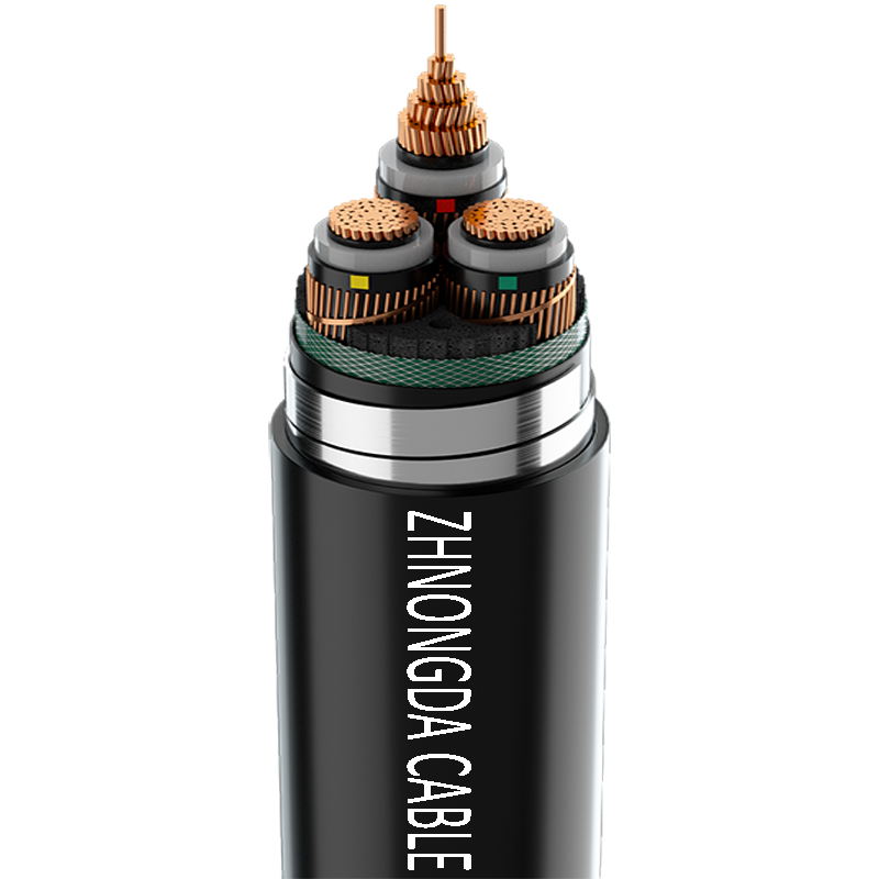
Direct burial utilizes heavily armored and jacketed cables laid directly in the earth. While it offers lower initial material costs, it is more vulnerable to physical damage from future excavations. Conduit encased systems involve pulling cables through pre-installed pipes made of PVC, HDPE, or rigid metal. This provides superior physical protection and allows for easier future upgrades without re-excavation. Concrete encasement, or duct banks, is required for high-voltage lines or areas with heavy surface loads like highway crossings or industrial facility entrances.
| Protection Method | Primary Advantage | Primary Disadvantage |
|---|---|---|
| Direct Burial | Lowest initial material and labor cost. | Zero protection against future dig-ins; requires full excavation to replace. |
| PVC / HDPE Conduit | Allows for easy cable replacement and upgrades. | Requires careful joint sealing and mandrel testing before pulling. |
| Concrete Duct Bank | Maximum physical protection and structural integrity. | Highly labor-intensive; requires rebar, formwork, and concrete pouring. |
Marine and port infrastructure present unique challenges that standard utility cables cannot survive. Installation parameters for a shore power cable focus on marine-grade jacketing, moisture barriers, and corrosion-resistant conduit systems to withstand constant salinity and tidal movements. These cables must endure harsh physical environments while delivering massive power to docked vessels. In high-water table zones, utilizing water-blocked cables with swellable tapes and sealed vault systems is necessary to prevent water ingress. If water travels down the conductor strands, it will inevitably cause a catastrophic electrical fault.
Using engineered thermal backfill, such as fluidized thermal backfill (FTB) or specific limestone sand mixtures, ensures optimal heat dissipation. Preventing thermal bottlenecks is a non-negotiable risk mitigation strategy. If heat cannot escape the conduit, it degrades the cross-linked polyethylene (XLPE) or ethylene propylene rubber (EPR) insulation. This significantly reduces the overall lifespan of the underground installation. Engineers calculate the exact thermal resistivity (rho value) of the native soil and specify the exact dimensions of the thermal backfill envelope required to keep the cables operating within their temperature limits.
Balancing the higher initial installation costs of undergrounding against long-term operational savings is a major consideration for utility planners. Underground installations often cost five to ten times more upfront than overhead lines due to excavation, specialized materials, and complex civil engineering. However, they offer massive savings from reduced storm-related outages, eliminated vegetation management, and improved grid resilience. This explains why most power lines aren't underground everywhere; the initial capital expenditure is simply too high for long rural stretches, but easily justified in hurricane-prone coastal cities.
While underground cables fail less frequently than overhead lines, maintenance presents entirely different challenges. Locating faults and executing repairs takes significantly longer. Visual inspections are impossible. Crews must use specialized diagnostic equipment, such as Time Domain Reflectometers (TDR) and capacitive discharge units (thumpers), to pinpoint issues beneath the surface. Once the fault is located, crews must excavate the area, cut out the damaged section, and build a new splice box, which can keep a circuit offline for days rather than hours.
Surface restoration costs and complex utility upgrades in urban environments often make HDD financially viable compared to open trenching. Tearing up a mile of city asphalt, managing traffic, and repaving the road is incredibly expensive. In contrast, rural accessibility allows for cheaper methods like plowing or open trenching, where surface disruption is less of a concern and heavy equipment has room to maneuver. The terrain dictates the tool.
Project managers must decide whether to size conduit for future capacity by leaving spare ducts or to realize immediate cost savings through exact-fit sizing. Installing a four-inch spare conduit during an open trench operation costs very little in materials. However, having to mobilize an HDD rig five years later to add a single circuit costs a fortune. Planning for future expansion, grid modernization, and increased load demands prevents costly re-excavation down the line.
Damaging existing water, gas, or telecommunications lines during excavation or drilling is a severe risk that can shut down a project and result in massive fines. Mandating non-destructive hydro-excavation for visual verification at all utility crossings is essential. Utilizing advanced GPR prior to breaking ground further mitigates this danger. Drill operators must physically see the existing utility in the pothole as the drill head passes by to guarantee clearance.
Heavy rainfall can cause trench collapse, while frozen ground can halt plow operations entirely. Implementing strict trench shoring protocols protects workers and maintains the integrity of the installation. Trench boxes or hydraulic shoring must be used in excavations deeper than five feet. Scheduling installations during optimal seasonal windows helps avoid costly weather-related delays. Pumping water out of flooded trenches slows down production and compromises the compaction of the thermal backfill.
Vetting engineering, procurement, and construction firms based on their specific experience is critical. Look for expertise in HDD telemetry, heavy civil concrete work, or high-voltage splicing, depending on the project scope. Mandating post-installation testing ensures quality before energizing the system. You must require Very Low Frequency (VLF) testing, pulling tension logs, and jacket integrity tests (megger testing). If a contractor exceeds the maximum pulling tension, the cable is compromised, even if it looks fine on the outside.
A: The primary barrier is the initial capital expenditure. Installing power lines underground typically requires five to ten times the upfront investment compared to overhead lines. This is due to heavy excavation, specialized materials, complex civil engineering, and expensive surface restoration.
A: The National Electrical Code generally requires a minimum depth of 24 to 36 inches for standard distribution. However, this depth varies significantly based on the system voltage, the type of conduit used, and the surface load conditions above the trench.
A: Trenching involves digging an open ditch, laying the conduit, and backfilling, which heavily disrupts the surface. Directional drilling uses a rig to bore a subterranean path and pull the cable through, leaving the surface completely undisturbed.
A: While technically possible with specific direct-burial ratings, shore environments typically require robust conduit systems and marine-grade jacketing. This infrastructure is necessary to protect the cable against constant moisture, high salinity, and physical damage from port operations.
A: Engineered thermal backfill, such as specific limestone sand mixtures or fluidized thermal backfill, is required. It ensures proper heat dissipation, preventing the cable insulation from overheating, degrading, and failing prematurely under heavy electrical loads.
A: They are protected using heavy-duty, moisture-resistant jacketing and water-blocked cable designs featuring swellable tapes. Additionally, they are installed within sealed conduit systems and terminated inside watertight underground splicing vaults.
 简体中文
简体中文 

