

Views: 0 Author: Site Editor Publish Time: 2026-08-28 Origin: Site


The transition from overhead lines to underground infrastructure is driven by the need for grid resilience, but the engineering complexity and capital requirements present significant barriers to entry. Decision-makers must balance the high upfront costs of burying utilities against long-term reliability, while navigating strict safety codes, thermal management challenges, and the physical risks of excavation. Unlike open-air systems, subterranean networks require meticulous planning regarding soil thermal resistivity, mechanical shielding, and precise routing to avoid existing subterranean hazards. Moving power distribution below grade eliminates wind and ice loading risks but introduces severe constraints regarding heat dissipation and water ingress. This guide provides a technical evaluation framework for underground power cable projects, detailing approved installation methodologies, compliance standards, and risk mitigation strategies necessary for successful deployment.
Defining the primary drivers for moving utilities below ground is the first step in project evaluation. Common catalysts include storm hardening in hurricane-prone regions, strict aesthetic requirements for new commercial developments, and spatial constraints in densely populated urban corridors. Establishing clear success criteria ensures that the engineering design aligns with the overarching goals of the development. If the primary goal is storm resilience, the system design must heavily prioritize water ingress prevention and robust mechanical shielding. Engineers must assess the specific load requirements, future capacity expansion needs, and the geological realities of the proposed route before committing to a subterranean design.
Project managers must also consider the operational environment. High-traffic urban areas require different success criteria than rural subdivisions. In a city center, minimizing surface disruption during construction might be the highest priority, pushing the design toward trenchless technologies. In a rural setting, raw material costs and trenching speed might dictate the approach. Defining these parameters early prevents scope creep and ensures the final infrastructure meets the exact needs of the utility and the end-users.
Analyzing the capital expenditure multiplier of undergrounding versus overhead lines is necessary. While the initial installation requires significant earthwork, specialized materials, and complex labor, these costs must be weighed against the reduction in operational expenditure. Buried systems experience significantly fewer storm-related outages, reducing emergency repair costs and minimizing downtime for end-users. The financial modeling must account for the extended lifespan of properly installed subterranean networks.
Utility companies track reliability using metrics like the System Average Interruption Duration Index (SAIDI) and the System Average Interruption Frequency Index (SAIFI). Undergrounding directly improves these metrics by removing the primary causes of faults: falling trees, high winds, and ice accumulation. However, the repair time for an underground fault is typically longer than an overhead fault because locating and excavating the damaged section requires specialized equipment and more labor hours. This trade-off between frequency and duration of outages must be modeled accurately.
| Metric | Overhead Systems | Underground Systems |
|---|---|---|
| Initial Capital Expenditure | Baseline | 3x to 10x Baseline |
| Fault Frequency (SAIFI) | High (Weather/Vegetation dependent) | Low (Protected from surface elements) |
| Fault Repair Duration (SAIDI) | Short (Visual inspection, easy access) | Long (Requires fault finding equipment, excavation) |
| Lifespan | 30-40 Years | 40-60 Years (with proper thermal management) |
It is a misconception that buried lines are entirely immune to failure. They remain susceptible to distinct environmental and human-made threats. Flooding and high water tables can cause water treeing in cable insulation over time. Seismic activity can shear conduits and fracture splice joints. Furthermore, third-party excavation damage, commonly known as dig-ins, remains a leading cause of subterranean utility failure. Acknowledging these limitations is critical for implementing adequate mechanical protection and monitoring systems.
Thermal runaway is another severe limitation. When conductors carry heavy loads, they generate heat. If the surrounding soil cannot dissipate this heat fast enough, the insulation degrades, eventually leading to a catastrophic short circuit. This requires precise engineering of the trench backfill and strict adherence to spacing requirements between parallel circuits. You cannot simply pack multiple high-voltage lines into a tight trench without risking a complete system meltdown.
In scenarios where full undergrounding is unfeasible due to impassable terrain or severe budget constraints, hybrid systems offer a practical compromise. Riser poles are utilized to transition from underground networks back to overhead lines. This approach is highly effective when crossing deep creeks, steep ravines, or major highway interchanges where horizontal directional drilling is structurally or financially prohibitive. Strategic transitions optimize project viability while maintaining continuous power delivery.
Designing a riser pole requires specific hardware, including surge arresters, potheads (terminations), and heavy-duty conduit sweeps to protect the line as it exits the earth. The transition point is a vulnerable node in the network, requiring robust grounding and physical protection from vehicular impact. Engineers must carefully calculate the tension and load on the riser pole to ensure it can support the weight of the transitioning cables and the associated hardware.
The traditional method for laying subterranean lines involves excavating a continuous trench along the designated route. Proper cable trench installation requires creating a perfectly smooth, debris-free trench bottom. Any sharp rocks or uneven grading can cause point-loading, leading to eventual jacket puncture and insulation failure. Once the trench is prepared, conduit or direct-burial lines are laid, followed by engineered backfilling.
This method is highly cost-effective for new developments with clear terrain and minimal existing infrastructure. However, it is highly disruptive in established urban environments, requiring road closures, pavement restoration, and extensive traffic management. A major advantage of open-cut trenching is scalability; it allows for the easy installation of spare conduits alongside the active lines, facilitating future capacity upgrades without requiring secondary excavation.
When executing an open-cut trench, contractors must manage the excavated spoil. Depending on the soil quality, the native earth may be reused as backfill, or it must be hauled away and replaced with engineered thermal sand. Trench shoring is also a critical safety requirement for excavations deeper than five feet, protecting workers from cave-ins while they lay the conduit and pull the lines.
Horizontal Directional Drilling is a trenchless technology utilizing a steerable drill to create a subterranean path for conduit insertion. The process begins with a pilot hole, which is subsequently enlarged using a reamer until it accommodates the required conduit size. Drilling fluid is used to stabilize the bore path, cool the drill bit, and remove cuttings.
While HDD carries a higher upfront equipment and labor cost, it is absolutely essential for crossing roadways, waterways, active railways, or environmentally sensitive areas. It eliminates surface disruption, thereby negating the costs associated with pavement restoration and minimizing public inconvenience. HDD requires highly skilled operators and precise geological surveying to avoid subterranean obstacles.
Selecting between direct burial and conduit-based systems impacts both initial material costs and long-term maintenance protocols. Direct burial involves placing heavily sheathed lines directly into the excavated trench. This method relies on the surrounding soil for physical protection and heat dissipation. Conduit systems involve laying PVC, HDPE, or fiberglass pipes first, and then pulling the lines through them.
| System Type | Mechanism | Advantages | Disadvantages |
|---|---|---|---|
| Direct Burial | Cables manufactured with heavy-duty sheathing are placed directly in the excavated earth. | Lower initial material cost; faster installation in clear terrain; better natural heat dissipation into surrounding soil. | Requires full excavation to repair, replace, or upgrade; highly vulnerable to dig-ins and rocky soil punctures. |
| Conduit Systems | Cables are pulled through PVC, fiberglass, or HDPE pipes laid in the trench or bored path. | Superior physical protection; allows for relatively easy cable replacement or upgrades without re-excavation. | Higher initial investment; conduit air gaps can trap heat, requiring careful thermal engineering and derating calculations. |
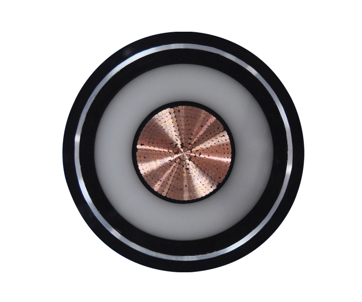
Soil acts as a thermal insulator. High-voltage transmission lines generate significant heat under heavy load, and this heat must dissipate into the surrounding earth to prevent the insulation from degrading or melting. If the soil cannot conduct heat away efficiently, the system will fail prematurely. The ability of soil to resist heat flow is measured in Rho (thermal resistivity).
Engineers must conduct thermal resistivity testing on the native soil along the proposed route. If the native soil is highly resistive (e.g., dry, loosely packed dirt), the trench must be filled with engineered thermal backfill. Fluid thermal backfill or specialized limestone sand is utilized to manage heat transfer, ensuring the lines operate within their designed temperature thresholds. Moisture content heavily influences Rho values; dry soil traps heat, while moist soil conducts it away. Therefore, drainage patterns around the trench must be evaluated.
Encountering solid rock formations or highly compacted, impenetrable soils during excavation drastically alters project timelines. Standard trenching equipment cannot bypass these obstacles. Solutions require mobilizing specialized rock trenchers or employing controlled blasting techniques. These interventions must be factored into project timelines, budget contingencies, and environmental impact assessments, as blasting requires strict regulatory oversight and vibration monitoring to protect nearby structures.
When blasting is not an option due to proximity to existing foundations or pipelines, contractors use heavy-duty rock saws or hydraulic hammers attached to excavators. This slows production rates significantly. The excavated rock cannot be used as backfill, meaning contractors must haul the rock off-site and import clean sand or flowable fill to bed the trench, further increasing material and transport costs.
Before any earth is moved, the Right-of-Way must be legally secured and physically prepared. This process involves clearing deep-rooted vegetation that could eventually compromise the cable jacket or conduit integrity. The installation path must be graded to allow heavy machinery access and ensure the final trench depth remains consistent relative to the finished surface grade.
Proper ROW preparation also involves establishing erosion control measures, such as silt fences and straw wattles, to prevent runoff into nearby waterways during excavation. Access roads may need to be built or reinforced with timber mats to support the weight of loaded reel trailers and excavators, especially in swampy or soft-soil environments.
Safe underground cable installation hinges on avoiding existing infrastructure. Striking a gas main or fiber optic line causes catastrophic safety hazards and massive financial liabilities. Mandatory coordination with local utility locators (such as 811 systems) is the baseline. Advanced risk mitigation requires ground-penetrating radar (GPR) and non-destructive vacuum excavation (potholing) to visually verify the exact depth and location of existing water, gas, and communication lines before heavy machinery begins digging.
Vacuum excavation uses high-pressure water or air to break up the soil, which is then sucked into a debris tank. This exposes the existing utility without the risk of a mechanical bucket tearing through it. Once the utility is visually confirmed, the contractor can safely route the new trench over or under the existing line, maintaining the required clearance distances mandated by local codes.
Compliance with the National Electrical Code (NEC) dictates standard minimum cover requirements. Typically, standard residential and commercial voltages require 18 to 24 inches of cover. However, this scales deeper for high-voltage transmission lines. Depth requirements also fluctuate based on the surface above the trench. Lines running under vehicular traffic require significantly deeper burial or concrete encasement compared to those under pedestrian pathways. The type of conduit used (e.g., rigid metal vs. PVC) also influences the legally required burial depth.
Maintaining clearance from other utilities is equally critical. The NEC and local utility standards dictate minimum separation distances between power lines and communication, water, or gas lines. This prevents induced voltage on communication lines and ensures safe access for future maintenance of adjacent utilities. If minimum separation cannot be achieved, specialized shielding or concrete barriers must be installed between the utilities.
Implementing robust buried cable protection is critical for long-term viability. The most basic layer is the installation of detectable warning tape placed approximately 12 inches above the utility line to alert future excavators before they strike the conduit. For high-voltage lines or areas with high dig-in risks, physical barriers are mandatory. This includes concrete encasement, known as duct banks, which provide impenetrable shielding. Additionally, sand bedding is used at the base of the trench to maintain a smooth bottom and prevent native rock from puncturing the jacket under the weight of the backfill.
Duct banks are constructed by laying multiple PVC conduits in a grid pattern using plastic spacers, then pouring concrete around the entire assembly. This provides maximum physical protection and ensures the conduits remain perfectly aligned. Red dye is often added to the concrete mix so future excavators immediately recognize they have hit a high-voltage electrical duct bank.
Electrical faults in subterranean systems must be managed safely to prevent surface-level shock hazards. Implementing proper grounding systems at all splices, vaults, and terminations is a strict safety protocol. These grounding arrays safely direct fault currents deep into the earth, triggering protective relays to de-energize the circuit, thereby protecting both maintenance personnel and connected grid infrastructure.
Grounding involves driving copper-clad steel rods into the earth inside the utility vaults and connecting them to the cable shields and splice hardware using heavy-gauge copper wire. The resistance of the grounding system must be tested using a fall-of-potential meter to ensure it meets the utility's specifications, typically requiring a resistance of 25 ohms or less.
A critical compliance checkpoint occurs immediately after the lines or conduits are laid but before the trench is filled. There is a mandatory requirement to halt work and have municipal inspectors or utility representatives visually verify the installation. They check trench depth, smooth bottom preparation, conduit integrity, and spacing. Backfilling before receiving this official sign-off often results in orders to re-excavate the entire line at the contractor's expense.
Inspectors will measure the depth from the top of the conduit to the final grade level. They will verify that the correct type of conduit was used for the specific application and that all joints are properly glued and sealed. They will also check the installation of warning tape and the quality of the sand bedding. Only after the inspector signs the permit can the contractor begin placing the final backfill and compacting the trench.
Prolonged exposure to high water tables or seasonal flooding presents a severe risk to any Underground Power Cable. Moisture penetration degrades insulation over time through a process called water treeing, eventually leading to a short circuit. Mitigation requires specifying water-blocked cables that contain swellable powders to halt moisture migration. Furthermore, conduit systems must be hermetically sealed at all joints, and subterranean vaults must feature proper drainage systems or sump pumps to prevent prolonged submersion of splice joints.
Vaults and manholes are particularly vulnerable to water accumulation. Even with sealed conduits, groundwater can seep through concrete joints or manhole covers. Regular maintenance programs must include pumping out vaults and inspecting splice enclosures for signs of moisture ingress or corrosion. Using submersible-rated splice kits provides an additional layer of defense against water damage.
The success of the project relies entirely on the competence of the installation contractor. Vetting criteria must be stringent. Project managers must verify required certifications and specific experience with the voltage classes being installed. If trenchless technology is required, the contractor should preferably own their HDD equipment rather than sub-contracting it, ensuring better quality control. Finally, evaluating verifiable safety records, specifically Experience Modification Rate (EMR) ratings, ensures the partner adheres to strict operational safety standards.
Contractors must also demonstrate proficiency in pulling heavy conductors without exceeding the maximum allowable pulling tension or sidewall pressure. Exceeding these limits stretches the copper or aluminum conductors and damages the insulation, leading to premature failure. The contractor must use calibrated pulling equipment, dynamometers, and appropriate cable lubricants to ensure a safe and compliant installation.
Safe and effective subterranean power installation requires balancing the high initial investment with rigorous site engineering, thermal management, and strict adherence to safety codes. Project managers should select installation methods based on surface disruption constraints and choose contractors with proven expertise in thermal backfill and strike prevention. To ensure project success, execute the following next steps:
A: Standard NEC requirements mandate 18 to 24 inches of cover for standard voltages. However, high-voltage lines, or those installed under vehicular traffic, require significantly deeper burial or concrete encasement to ensure mechanical protection and safety.
A: Overhead lines rely on ambient air for cooling. Buried environments trap heat. Therefore, subterranean lines require specialized, thick insulation and engineered thermal backfill to dissipate heat safely and prevent the conductors from melting.
A: Direct burial places heavily sheathed lines directly in the earth, offering lower upfront costs but difficult maintenance. Conduit installation pulls lines through protective pipes, requiring a higher initial investment but allowing for easier replacement and superior physical protection.
A: Contractors must use 811 locating services, ground-penetrating radar, and non-destructive vacuum excavation to visually verify the exact depth and location of existing water, gas, and communication lines before heavy digging begins.
A: Protection strategies include detectable warning tape placed above the utility, PVC or HDPE conduit, sand bedding to prevent rock punctures, and concrete encasement for high-voltage or high-risk zones.
A: Rocky soil complicates excavation, often requiring controlled blasting or specialized rock trenchers. Additionally, highly resistive soils trap heat, requiring the importation of engineered thermal backfill to allow the utility lines to dissipate heat safely.
A: No. Trenches must remain open until a municipal inspector or local utility representative has visually reviewed and approved the installation depth, bedding, and conduit integrity. Backfilling prematurely violates safety codes.
 简体中文
简体中文 

