

Views: 0 Author: Site Editor Publish Time: 2026-08-28 Origin: Site


The integrity of any electrical infrastructure relies heavily on its connection points. Improperly specified or executed connections lead to thermal runaway, arc flashes, unplanned operational downtime, and catastrophic equipment failure. For commercial and industrial facilities, the operational impact of a connection failure far exceeds the initial material investment. Evaluating the correct methodology for a Power Cable Connection requires balancing voltage requirements, environmental stressors, and lifecycle maintenance. This guide breaks down connection methodologies across various applications, from low-voltage facility distribution to heavy industrial splices. We cover technical evaluation criteria and the critical role of condition monitoring in high-stakes environments. Proper execution at the connection point ensures long-term safety and system reliability.
Understanding the physical and electrical components of a connection is vital for field engineers and technicians. Every joint or termination must seamlessly continue the electrical and mechanical properties of the original cable. Failure to replicate these properties introduces vulnerabilities into the network. We see this often in industrial settings where rushed installations bypass basic anatomical requirements of the cable structure.
The first step involves tracing circuits within junction boxes. You must verify hot, neutral, and ground wire configurations. This ensures safe, compliant bonding and accurate phase alignment. Incorrect phasing leads to immediate short circuits or catastrophic equipment damage upon energization. Technicians use specialized tracing tools, like tone generators and digital multimeters, to confirm paths before making any physical cuts. Proper identification prevents cross-wiring and phase-to-ground faults. In three-phase systems, verifying A-B-C rotation is mandatory before finalizing any mechanical lug tightening.
The conductor interface is the physical meeting point of copper or aluminum conductors. You must remove all oxidation before joining the metals. Aluminum forms a highly resistive oxide layer almost instantly upon exposure to air. Utilizing oxide-inhibiting compounds is mandatory, especially when joining dissimilar metals. This compound prevents galvanic corrosion and maintains a low-resistance pathway for current flow. Field crews should use wire brushes dedicated specifically to either copper or aluminum to avoid cross-contamination during the cleaning phase.
Stripping a cable removes its primary dielectric barrier. The connection must replicate the dielectric strength of the original cable jacket. This prevents leakage current and protects against environmental ingress. Technicians use specialized tapes, heat-shrink tubing, or cold-shrink sleeves to rebuild this layer. The reconstructed insulation must withstand the system's maximum operating voltage without breaking down over time. For medium voltage applications, this often involves applying semi-conducting tape followed by high-voltage EPR tape, stretched to exactly half its original width to eliminate air voids.
Managing electrical stress at the termination point is a primary concern in medium and high-voltage applications. Electric fields concentrate at the edge of the insulation shield. Without proper stress control, this concentration exceeds the dielectric strength of the surrounding air or insulation. This leads to partial discharge and eventual flashover. Stress cones or high-permittivity stress control tubes distribute these electrical fields safely. Installers must measure the cutback dimensions down to the millimeter, as specified by the termination kit manufacturer, to ensure the stress tube overlaps the semi-con layer correctly.
Medium and high-voltage cables feature metallic shields to confine the electric field. Ensuring the continuity of this metallic shield across the connection is non-negotiable. Ground wires must also be properly bonded. This safely manages fault currents and prevents localized heating. A compromised shield connection can elevate touch potentials, creating severe safety hazards for personnel working near the cable. Constant force springs or soldered copper braids typically bridge the shield gap across a splice.
Different environments and voltage levels demand specific connection strategies. Selecting the wrong methodology compromises system integrity and safety. Field conditions often dictate which method is practical, balancing speed, reliability, and available tooling.
Low-voltage systems rely on standardized interfaces for safety and convenience. These connections facilitate rapid deployment and maintenance in commercial buildings and light industrial floors.
Mechanical connectors offer flexibility in the field without requiring heavy hydraulic tools. They rely on threaded mechanisms to secure the conductors, making them popular for panel terminations.
Compression fittings create a permanent, low-resistance joint. They are a staple in industrial and utility applications where vibration or high current loads are present.
Exothermic welding provides the ultimate permanent connection. It physically merges the conductors into a single mass, primarily used in grounding grids.
Understanding the distinction between splicing and terminating is fundamental to cable management and procurement.
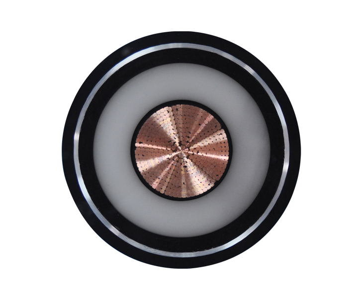
Selecting the right connection involves a systematic evaluation of electrical, mechanical, and environmental factors. A structured decision framework prevents costly specification errors and ensures the installation matches the operational reality of the site.
| Evaluation Criteria | Key Considerations | Impact on Connection Choice |
|---|---|---|
| Circuit Tracing | Identify source and destination paths accurately. | Prevents cross-wiring and phase-to-ground faults before execution. |
| Voltage & Load | Continuous current ratings and short-circuit faults. | Connection must meet or exceed the ampacity of the cable. |
| Moisture/Submersion | Exposure to water or high humidity. | Requires resin-filled joints or adhesive-lined heat shrink. |
| Vibration | Mechanical movement from nearby machinery. | Dictates compression fittings over standard mechanical lugs. |
| Installation Velocity | Time constraints and confined space limitations. | Cold shrink offers faster, safer installations than heat shrink. |
Implementing systematic wire tracing protocols is mandatory. You must definitively identify source and destination paths in complex junction boxes before executing a connection. This prevents cross-wiring and phase-to-ground faults. Accurate tracing ensures that the subsequent connection handles the intended load without unexpected phase imbalances. Field crews should utilize lockout/tagout (LOTO) procedures in conjunction with tracing to guarantee the circuit is de-energized.
Assess continuous current ratings and short-circuit fault current capabilities. The connection must meet or exceed the ampacity of the cable itself. An undersized connector becomes a bottleneck. It generates excessive heat during peak loads, leading to accelerated insulation degradation and eventual failure. Always verify the lug or splice rating against the breaker size, not just the cable gauge.
The operating environment dictates the outer protection of the connection. Moisture and submersion require resin-filled joints or heavy-wall adhesive-lined heat shrink to prevent water ingress. High-vibration environments demand compression fittings, as mechanical lugs may vibrate loose. Chemical exposure requires selecting appropriate polymeric materials for the outer sealing sleeve to prevent chemical degradation. Direct burial applications require robust mechanical protection against soil settlement and rock impingement.
Project timelines often dictate connection choices. Cold shrink terminations offer faster, safer installations in confined spaces compared to heat shrink or taped connections. They do not require open flames or heat guns. This reduces labor hours and minimizes human error during the installation process. The unwinding core mechanism of cold shrink allows for consistent radial pressure without relying on the installer's heating technique.
Ensure all selected components are rigorously tested. Splices should meet IEEE 404 standards, while terminations must comply with IEEE 48. Equivalent IEC and UL standards also apply depending on your region. Utilizing certified components guarantees baseline performance and safety under specified operating conditions. Non-compliant knock-off connectors often use inferior metal alloys that fail under heavy load cycling.
Static testing during commissioning only proves the connection works at that specific moment. Long-term reliability requires continuous oversight. Implementing High Voltage Cable Monitoring transforms maintenance from reactive to predictive, saving facilities from catastrophic unplanned outages.
Baseline commissioning tests, such as VLF (Very Low Frequency) or Megger testing, are essential but insufficient for long-term reliability. They provide a snapshot of insulation integrity. However, they cannot predict how a connection will degrade under continuous thermal cycling, electrical stress, and environmental exposure in medium to high-voltage networks. A splice that passes a VLF test today can still fail six months later due to microscopic moisture ingress.
Continuous PD monitoring is a game-changer for connection health. It detects microscopic voids, tracking, and insulation degradation specifically at splices and terminations. These tiny discharges emit high-frequency signals. Monitoring systems capture these signals before the degradation escalates into a catastrophic flashover. Early detection allows for scheduled repairs rather than emergency outages. PD sensors can be permanently installed at termination points inside switchgear for 24/7 data collection.
Thermal anomalies are the earliest indicators of connection failure. Utilizing fiber optic sensors allows operators to monitor the thermal profile of the entire cable run. DTS pinpoints localized hotspots at connection points caused by high resistance. Identifying a degrading, high-resistance joint early prevents thermal runaway and subsequent fires. This is particularly useful in long underground duct banks where visual inspection is impossible.
Transitioning from reactive repairs to predictive maintenance yields massive financial benefits. Continuous monitoring extends asset lifespan. It prevents millions of dollars in unplanned outage costs, equipment replacement, and lost production. The initial investment in monitoring hardware is quickly offset by the avoidance of a single major failure. Facilities can schedule maintenance during planned shutdowns based on actual asset condition rather than arbitrary calendar dates.
Even with the right components, poor execution introduces severe risks. Recognizing these pitfalls and enforcing strict mitigation strategies is essential for connection longevity. Field supervision plays a massive role in ensuring these mitigations are actually applied.
Galvanic corrosion occurs when joining dissimilar metals, such as copper to aluminum, without proper bimetallic transition connectors. The presence of moisture acts as an electrolyte, accelerating the corrosion of the aluminum conductor. This rapidly increases joint resistance, leading to overheating and failure.
Mechanical connections are highly sensitive to torque. Under-torqued bolts cause high resistance and excessive heat. Over-torqued bolts crush and damage the conductor strands, weakening the physical joint. Thermal cycling causes standard bolts to loosen over time as the metals expand and contract at different rates.
Medium and high-voltage connections are incredibly sensitive to contamination. Dirt, moisture, or even sweat introduced during the preparation of splices creates tracking paths. These paths compromise the dielectric strength and lead to premature failure. A single fingerprint on the semi-con cutback can cause a flashover.
A reliable connection is not merely a physical link. It is a highly engineered system designed to manage electrical stress, thermal expansion, and environmental ingress across all voltage classes. Treating connections as critical infrastructure components is the only way to ensure network stability.
For low-voltage commercial applications, standardized couplers and mechanical lugs offer sufficient reliability. However, for medium to high-voltage industrial and utility applications, the specification must shift. You must rely on cold-shrink terminations, shearbolt technology, and rigorous stress control to maintain safety and performance.
To improve your electrical infrastructure reliability immediately, take the following actions:
A: A splice connects two cables end-to-end to extend their length or repair a fault, requiring full reconstruction of all cable layers. A termination connects a cable to equipment like switchgear or motors, focusing primarily on electrical stress relief and environmental sealing at the cable end.
A: Technicians use specialized circuit tracers, tone generators, and multimeters to verify the source and destination of wires within a junction box. This process confirms hot, neutral, and ground configurations, preventing cross-wiring and dangerous phase-to-ground faults.
A: The hot wire carries the electrical current from the source to the load. The neutral wire provides the return path to complete the circuit. The ground wire acts as a safety mechanism, providing a safe path for fault currents to earth, preventing electric shock.
A: Most failures stem from poor installation practices rather than defective hardware. Common causes include inadequate insulation stripping, failure to remove oxidation, improper torque on mechanical lugs, and contamination by dirt or moisture during the splicing process.
A: Cold shrink is preferred in confined spaces or hazardous environments where open flames are prohibited. It installs faster and provides a consistent radial pressure that expands and contracts with the cable during thermal cycling.
A: Monitoring systems use sensors to detect partial discharge and abnormal temperature increases. These anomalies indicate a deteriorating connection long before a catastrophic failure occurs, allowing for planned maintenance.
A: Galvanic corrosion happens when dissimilar metals, like copper and aluminum, are joined directly in the presence of moisture. This causes the aluminum to corrode rapidly, increasing electrical resistance. It is prevented by using bimetallic lugs and oxide-inhibiting compounds.
 简体中文
简体中文 

