

Views: 0 Author: Site Editor Publish Time: 2026-08-25 Origin: Site


Swapping components, executing a PC case swap, or preparing older hardware for resale often leaves users with a surplus of leftover cables. While reusing them seems efficient, incorrectly swapping power delivery components is a leading cause of catastrophic hardware failure, electrical fires, and voided warranties. The physical fit of a connector does not guarantee electrical compatibility. Standardized component-side connectors often mask proprietary power-supply-side pinouts. Identical-looking exterior cables can possess vastly different thermal and amperage thresholds.
This guide provides a definitive technical evaluation framework. You will learn how to determine when it is safe to reuse a Power Cable, when OEM replacements are mandatory, and how to assess compatibility across consumer PCs, enterprise data centers, and industrial infrastructure.
The primary criteria for safe cable interchangeability is matching the exact electrical delivery requirements of the original equipment. You must verify voltage, amperage, and pinout mapping rather than merely achieving a physical connection. A plug that slides easily into a socket provides zero assurance that the wiring behind it aligns with the hardware's power phase design. Field technicians see this constantly. Someone forces a connector that looks right, flips the switch, and hears a pop.
Power cables must be categorized into two distinct groups before evaluation. Internal DC modular cables are highly device-specific. External AC mains cables are standardized physically but rated differently for electrical load. Mixing these categories up during troubleshooting leads to severe diagnostic errors. You have to know exactly what you are holding before you plug it into a wall or a motherboard.
Assessing the risk profile reveals stark differences between cable types. A mismatched external cable may cause a system to shut down under load or overheat due to resistance. Conversely, a mismatched internal modular cable will actively drive 12V power into a 5V component. This results in permanent hardware death, instantly destroying motherboards and storage drives. The stakes are incredibly high for internal wiring.
The illusion of compatibility stems from the hardware side. PCIe, SATA, and EPS connectors are strictly standardized on the motherboard and GPU side. Every graphics card expects the 12V and ground pins to be in the exact same location on an 8-pin connector. If they were not, building a PC would be impossible.
However, there is a complete lack of standardization on the PSU side. Manufacturers route voltages differently across the physical pins on the PSU housing. The 3.3V, 5V, 12V, and Ground wires cross over one another inside the cable sleeve to reach the standardized layout on the component end. Plugging a random cable into a PSU bypasses this specific routing logic. You are essentially playing Russian roulette with your hardware.
To illustrate this, consider how a standard 24-pin ATX cable functions. On the motherboard side, pin 16 is always the Power-On signal. On the PSU side, that same signal might be routed to pin 10, pin 14, or somewhere else entirely depending on the manufacturer's internal circuit board layout. There is no governing body forcing power supply makers to standardize the unit-side connections.
Mixing brands during case swaps or upgrades introduces extreme risk. Taking an EVGA cable and plugging it into a Corsair or Seasonic power supply will almost certainly cross a live voltage line with a ground line. This triggers an immediate short circuit upon powering the system. The over-current protection might save you, but often the damage happens faster than the protection can trip.
The dangerous community misconception that cables from the same manufacturer are universally interchangeable must be debunked. Generational updates often result in a loss of backwards compatibility. Manufacturers change internal platforms and OEM suppliers frequently. For example, Corsair Type 3 and Type 4 cables have different 24-pin ATX pinouts despite looking identical externally. Assuming they match just because of the logo is a costly mistake.
The only safe method for reusing modular cables is verifying exact model numbers. You must cross-reference your specific PSU model against the manufacturer’s official cable compatibility matrix. Guessing based on brand name alone is a guaranteed path to hardware failure. If you cannot positively identify the cable's origin, throw it in the recycling bin.
Third-party solutions require careful evaluation. Companies like CableMod produce high-quality alternatives, but you must order the exact kit designated for your specific PSU model. Generic kits do not exist for direct PSU connections. When ordering, you select your exact power supply model from a dropdown menu so the vendor can map the pins correctly at the factory.
You must distinguish between cable extensions and direct replacement cables. Extensions are universally compatible because they plug into the standard component ends of your existing cables. They simply act as a bridge. Direct replacement cables plug straight into the power supply and must be strictly PSU-specific. Mixing up these two concepts leads to catastrophic build failures.
The standard "kettle lead" or PC power cable utilizes the IEC C13 connector, mating with a C14 inlet. These are ubiquitous across desktop computers, monitors, and printers. The physical dimensions are internationally standardized. You can take a cable from a 1995 printer and physically plug it into a 2024 gaming PC.
While these are highly interchangeable physically, they are not universally rated for the same power draw. A cable bundled with a low-power office monitor uses thinner internal wiring than a cable supplied with a high-end workstation. Treating them as identical creates significant thermal hazards. The physical connector is just a shell; the copper inside does the actual work.
You must read the cable jacket to decode its capacity. Look for the AWG (American Wire Gauge) rating or the cross-sectional area in square millimeters (mm²). This printed specification dictates the maximum safe continuous load. It is usually stamped into the rubber every few feet.
Lower AWG numbers indicate thicker wires capable of handling higher amperage. An 18 AWG cable is thinner and handles less current than a 14 AWG cable. Thicker conductors reduce electrical resistance, preventing the cable from heating up under sustained heavy loads. Here is a practical breakdown of common gauges found in IT environments:
| Wire Gauge (AWG) | Typical Max Amperage | Common Application | Risk if Overloaded |
|---|---|---|---|
| 18 AWG | 10 Amps | Monitors, Basic Office PCs | Insulation melting, fire |
| 16 AWG | 13 Amps | Mid-range Workstations | Severe overheating |
| 14 AWG | 15 Amps | High-end Gaming PCs, Servers | Voltage drop, instability |
| 12 AWG | 20 Amps | Heavy Duty PDUs, UPS Systems | Breaker tripping |
Using an 18 AWG cable designed for a 30W monitor on a 1000W workstation PSU creates a severe thermal bottleneck. The cable will draw more current than its physical mass can safely conduct. This melts the insulation and creates an immediate fire hazard. Never use a thin cable for a heavy load.
Regional power grids heavily impact cable selection and amperage draw. North America operates on 110V, while Europe and Asia operate on 220V. A system drawing 1000W at 110V pulls roughly 9 amps. The same system at 220V pulls only 4.5 amps. This fundamental physics principle changes how you select wiring.
Cables used in 110V regions must often be thicker (lower AWG) to handle the higher amperage required to deliver the same total wattage. Always verify that the cable's voltage and temperature ratings exceed your local grid specifications. A cable rated for 10A at 250V is fine for a European server room, but might struggle with the amperage demands of a massive 110V American rendering farm.
Enterprise environments transition from consumer C13 to high-draw standards like C19/C20 connectors. These are designed for blade servers and heavy-duty Power Distribution Units (PDUs). They handle 16 to 20 amps continuously without degradation. The physical connectors are larger and squared off to prevent accidental insertion into lower-rated sockets.
Locking power cables become a necessity in high-vibration or mission-critical server racks. Accidental disconnects during maintenance cause unacceptable downtime. Specialized locking mechanisms ensure the connection remains secure regardless of physical disruption. Technicians working in dense racks frequently bump into wiring; locking cables prevent a simple bump from taking down a database.
Industrial power transmission requires entirely different parameters. Heavy-duty infrastructure relies on specialized conductors to move massive amounts of energy over long distances. The insulation and shielding requirements are exponentially stricter. You are no longer dealing with simple PVC jackets.
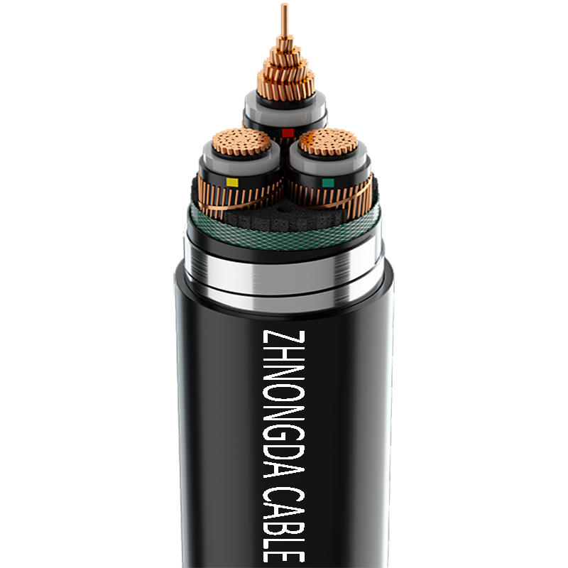
An Ultra High Voltage Power Cable utilizes cross-linked polyethylene (XLPE) insulation and robust metallic shielding. This differentiates it entirely from standard enterprise wiring. These cables must withstand extreme environmental stress, moisture ingress, and thermal expansion. They are engineered for substations and heavy manufacturing plants.
The catastrophic consequences of dielectric breakdown cannot be overstated. If voltage ratings are exceeded in industrial applications, the insulation fails. This results in massive arc flashes, infrastructure destruction, and severe safety hazards for on-site personnel. Industrial compatibility requires rigorous engineering sign-off, not just a visual check.
Enterprise procurement relies heavily on strict certifications. UL (Underwriters Laboratories), CE, and RoHS marks are mandatory for deployment. These certifications guarantee the cable has passed rigorous thermal and electrical stress testing. They are not just suggestions; they are legal requirements in many jurisdictions.
Uncertified, grey-market cables routinely fail compliance audits. Deploying them immediately voids enterprise hardware warranties. Insurance policies often reject claims if uncertified power delivery components are found to be the root cause of a facility fire. Always source wiring from authorized distributors who can provide documentation.
Determine immediately if the cable is AC (wall-to-device) or DC (internal modular). AC cables require gauge verification. DC cables require strict pinout and model verification. Never proceed without establishing this baseline classification. Look at the connectors: if it has a wall plug on one end, it is AC. If it has plastic Molex-style connectors on both ends, it is DC.
For AC cables, match or exceed the original AWG and amperage rating. If the original was 16 AWG, the replacement must be 16 AWG or 14 AWG. Never go to a higher number (thinner wire). For DC cables, consult the OEM compatibility chart directly. Do not rely on forum posts or visual similarities. Go to the manufacturer's website and find the exact matrix for your unit.
Advanced users and technicians use a digital multimeter to safely verify cables. Set the multimeter to continuity mode. You must map the pinouts of the known good original cable and document where each wire terminates. This requires patience and a steady hand.
Compare this map to the replacement cable before deploying it to live components. If the continuity map does not match perfectly, the cable is incompatible and must be discarded. Even one crossed wire will destroy your system.
Prioritize OEM direct replacements whenever possible. Certified aftermarket brands with explicit compatibility guarantees are acceptable secondary options. Always utilize authorized enterprise distributors over generic marketplaces to avoid counterfeit wiring. Counterfeit cables often print fake AWG ratings on the jacket, hiding dangerously thin copper inside.
A: Only if the monitor cable's AWG rating matches or exceeds the requirements of your PC. Monitor cables are often 18 AWG, which is too thin for high-wattage PC power supplies and can cause overheating. Always check the printed rating on the cable jacket.
A: No. Manufacturers frequently change internal pinout layouts between different product lines and generations. For example, Corsair Type 3 and Type 4 cables have different 24-pin layouts. You must consult the manufacturer's specific compatibility matrix.
A: Using the wrong modular cable routes incorrect voltages to your components. Sending 12V down a 5V line will instantly destroy connected hardware, including motherboards, graphics cards, and storage drives. The damage is permanent and voids warranties.
A: Look closely at the rubber jacket of the cable. You will find printed or embossed text indicating the AWG (American Wire Gauge) or mm² cross-section, alongside maximum voltage and temperature ratings. Lower AWG numbers mean thicker, higher-capacity wires.
A: A replacement cable plugs directly into the power supply and must be perfectly matched to the PSU's proprietary pinout. A cable extension plugs onto the end of your existing cables, acting as a bridge to the component. Extensions are universally compatible.
 简体中文
简体中文 

