

Views: 0 Author: Site Editor Publish Time: 2026-09-14 Origin: Site


Marine and offshore environments present severe operational challenges. Electrical system failures in these settings go beyond simple inconveniences; they create immediate safety hazards for the entire vessel. Specifying wiring for shipboard applications requires navigating complex engineering constraints. The infrastructure must withstand continuous saltwater exposure, heavy mechanical vibration, and strict international fire safety mandates. Failing to meet these demands leads to project delays, as inspectors will halt operations for non-compliance. Engineering and procurement teams need a clear methodology to navigate international standards, assess technical specifications, and vet suppliers. This guide provides a technical evaluation framework to help you specify the exact Marine Control Cable required for your application, ensuring your maritime systems remain safe, compliant, and fully operational.
Standardization is Non-Negotiable: IEC 60092-376 serves as the baseline standard for marine control cables, dictating voltage ratings (up to 250V) and temperature thresholds (typically 90°C).
Fire Safety Dictates Material Selection: SOLAS regulations mandate specific flame-retardant, low-smoke, zero-halogen (LSZH) materials to prevent toxic gas emissions in confined shipboard spaces.
Mechanical Resilience Equals Longevity: Proper specification requires balancing flexibility for installation in tight bulkheads with robust armoring to withstand continuous maritime vibration.
SWaP Optimization is Critical: Selecting cables with optimized size and weight profiles reduces overall vessel tonnage and eases installation in congested trays.
Vendor Vetting Mitigates Risk: Selecting a certified marine cable manufacturer with recognized Class Society approvals (e.g., DNV, ABS, Lloyd's Register) is as critical as the cable's technical specifications.
Saltwater acts as a highly conductive electrolyte. When moisture breaches a standard outer sheath, it initiates galvanic corrosion between the armoring and the copper conductors. This process accelerates rapidly in high-humidity areas like engine rooms and bilge spaces. Once the copper oxidizes, electrical resistance increases, leading to signal degradation and eventual circuit failure. Standard industrial wiring lacks the specialized jacket compounds required to repel this continuous moisture ingress.
Thermal cycling presents another physical challenge. Vessels frequently transit between freezing arctic conditions and high-temperature tropical zones. These extreme temperature fluctuations force the insulation materials to expand and contract repeatedly. Over time, this thermal stress causes standard PVC insulation to lose its plasticizers. The material becomes brittle, cracks under vibration, and exposes the live conductors. Furthermore, offshore platforms and engine rooms expose wiring to aggressive hydrocarbons, drilling muds, and synthetic lubricants. When petroleum-based fluids contact non-rated insulation, the polymers swell, soften, and dissolve, leading to immediate ground faults.
Classification societies enforce strict regulations to maintain maritime safety. Operating a vessel without proper certification from recognized authorities is illegal. Port State Control officers conduct routine inspections and will detain ships that utilize unapproved electrical components. During the shipbuilding phase, classification surveyors inspect cable runs before bulkheads are sealed. If they identify non-compliant wiring, they will issue a stop-work order.
The operational penalties for these failures are severe. Ripping out miles of unapproved wire from congested trays destroys construction schedules and inflates labor costs. Beyond regulatory detention, the physical failure of a control line cascades through the ship's architecture. Modern vessels rely on integrated automation systems. A single short circuit in a control line can disable dynamic positioning (DP) systems, causing a drillship to drift off its wellhead. It can sever communication between the bridge and the steering gear, or disable fire suppression alarm networks. Specifying the correct materials upfront is the only effective way to mitigate these operational hazards.
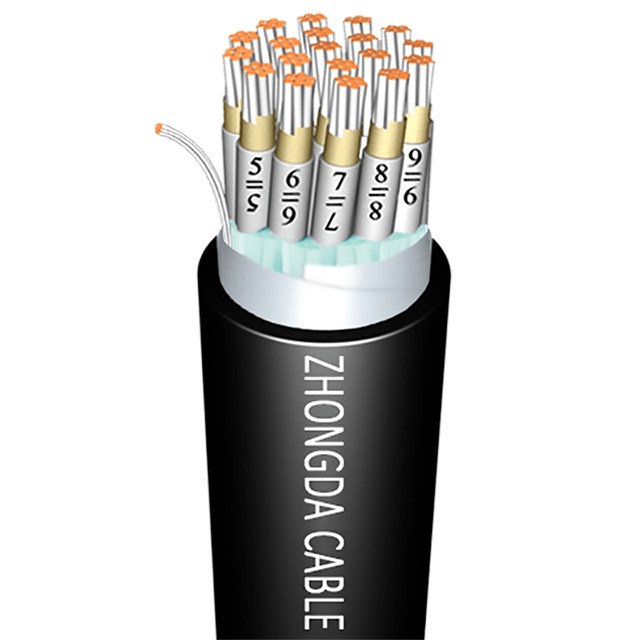
The International Electrotechnical Commission (IEC) 60092-376 standard dictates the design, construction, and testing parameters for control and instrumentation cables used on ships. This standard establishes the fundamental electrical and thermal baselines required for safe maritime operation. It specifies a maximum rated voltage of 150/250V. While control signals operate at low voltages, the insulation must withstand potential voltage spikes and maintain absolute signal stability across long distances.
IEC 60092-376 also mandates a maximum continuous conductor temperature of 90°C. This thermal rating ensures the wiring can handle its designated electrical load without the insulation melting or degrading over time. The standard outlines specific requirements for conductor stranding, insulation thickness, and the application of metallic screens for electromagnetic shielding. Engineering teams must verify that every control line specified for a project explicitly lists compliance with this specific IEC standard on its technical datasheet.
The Safety of Life at Sea (SOLAS) convention heavily influences electrical procurement. Fire represents the most severe hazard on any vessel. SOLAS Chapter II-1 and II-2 mandate strict fire safety protocols for all shipboard electrical installations. Cables supporting emergency systems must maintain circuit integrity during an active fire. This ensures that emergency lighting, fire pumps, public address systems, and watertight door controls remain functional while the crew responds to the incident.
SOLAS regulations also require the use of materials that actively prevent flame propagation. Fire must not travel along cable trays from one watertight compartment to another. The regulations outline specific testing criteria for flame retardancy, typically referencing IEC 60332-3-22 for bunched cables. Specifying wiring that meets these SOLAS requirements is a mandatory legal obligation for all commercial tonnage, passenger vessels, and offshore platforms.
Depending on the vessel's flag state and operational jurisdiction, procurement teams must often cross-reference regional standards. American-flagged vessels frequently require compliance with UL 2250 or the National Electrical Code (NEC) alongside international maritime rules. European shipyards often specify British Standards (BS) or European Norms (EN), such as BS-EN-50288. Understanding these regional equivalents prevents compliance disputes during final commissioning.
Specialized industry standards also dictate material selection in specific sectors. For offshore oil and gas platforms, engineers frequently reference EIL 52-46 for instrumentation lines. The NEK 606 standard is heavily utilized in the North Sea and globally for vessels requiring highly mud-resistant wiring. When local codes conflict with international maritime laws, a strict hierarchy applies. The strictest Class Society rules generally take precedence to ensure maximum safety. Engineering teams should consult their classification surveyor early in the design phase when overlapping standards create ambiguity.
Marine cable jackets and spec sheets feature specific alphanumeric codes that denote the construction materials. Reading these symbols accurately is a necessary skill for procurement and engineering personnel. These codes reveal the conductor type, insulation material, armor style, and outer sheath composition. Relying on a supplier's general marketing description often leads to purchasing the wrong specification.
For example, a common designation might indicate a stranded tinned copper conductor, cross-linked polyethylene insulation, a galvanized steel wire braid, and a halogen-free outer sheath. Understanding these designations guarantees the physical product matches the electrical engineering schematics. Procurement teams must verify the printed nomenclature on the technical datasheet before issuing a purchase order.
Abbreviation / Code | Component Description | Typical Marine Application |
|---|---|---|
TC | Tinned Copper Conductor | Prevents oxidation in high-humidity marine environments. |
XLPE | Cross-linked Polyethylene Insulation | Provides high thermal stability (90°C) and excellent dielectric strength. |
EPR | Ethylene Propylene Rubber Insulation | Offers superior flexibility for tight routing and cold-weather installations. |
GSWB | Galvanized Steel Wire Braid | Delivers heavy-duty mechanical protection against crushing and impacts. |
TCWB | Tinned Copper Wire Braid | Provides electromagnetic interference (EMI) shielding for sensitive signals. |
SHF1 | Halogen-free Thermoplastic Sheath | Standard LSZH outer jacket for general shipboard areas. |
SHF2 | Halogen-free Thermosetting Sheath | Heavy-duty LSZH jacket with enhanced oil and mud resistance. |
Matching the voltage grading to the control system's load requirements prevents electrical breakdowns. While 150/250V is the standard rating for marine control lines, the actual current load dictates the required conductor cross-section. Undersized conductors overheat, melt their insulation, and cause short circuits. Oversized conductors add unnecessary weight, increase the outer diameter, and inflate project costs.
Derating factors must be applied in maritime settings. High ambient temperatures in engine rooms significantly reduce a cable's effective current capacity. Bundling multiple lines tightly in congested trays restricts heat dissipation, further lowering the safe operating current. Engineering teams must adjust their capacity calculations to account for these environmental realities.
Determine the base current-carrying capacity of the selected conductor size at a standard 45°C ambient temperature.
Identify the maximum ambient temperature of the specific installation area (e.g., engine rooms may reach 55°C or higher).
Apply the temperature correction factor provided by the IEC 60092-201 standard to reduce the base capacity.
Count the number of cables bundled together in the designated cable tray or transit.
Apply the grouping correction factor to account for restricted heat dissipation among bundled lines.
Verify that the final derated current capacity still exceeds the maximum load of the control circuit.
The choice of insulation material directly impacts the cable's thermal stability and physical flexibility. XLPE (Cross-linked Polyethylene) and EPR (Ethylene Propylene Rubber) are the most common marine-grade options. The cross-linking process in XLPE changes the molecular structure of the plastic, making it highly resistant to heat deformation. It maintains excellent dielectric strength even at its maximum continuous operating temperature of 90°C.
EPR provides superior flexibility compared to XLPE. This flexibility is highly advantageous during installation in freezing offshore environments or when routing through tight bulkheads. Both materials meet the standard 90°C continuous operating temperature required by IEC standards. Specifying the correct insulation class ensures the material withstands peak operating temperatures without degrading. Engineers must balance the need for material flexibility against specific chemical resistance requirements based on the installation zone.
Insulation Material | Thermal Stability | Flexibility | Primary Marine Application |
|---|---|---|---|
XLPE (Cross-linked Polyethylene) | Excellent (Up to 90°C continuous) | Moderate | General shipboard control and power systems. |
EPR (Ethylene Propylene Rubber) | Very Good (Up to 90°C continuous) | High | Tight bulkheads and cold-weather environments. |
HEPR (Hard Ethylene Propylene Rubber) | Excellent (Up to 90°C continuous) | Moderate to High | High-stress mechanical areas requiring tough insulation. |
Mechanical protection is necessary to survive the physical abuse of a maritime environment. Galvanized steel wire braid (GSWB) offers robust physical defense against blunt impacts, crushing forces, and abrasion during installation. For control cables carrying sensitive low-voltage signals, electromagnetic interference (EMI) shielding is required. Tinned copper wire braid (TCWB) provides excellent EMI shielding alongside moderate physical protection. Without proper shielding, heavy power lines running in adjacent trays will induce voltage spikes and corrupt the data transmission in the control lines.
Vibration resistance is a major factor in engine rooms, thruster compartments, and near heavy rotating machinery. The continuous micro-vibrations generated by diesel engines travel throughout the steel hull. If the conductors are too rigid, these vibrations cause metal fatigue, leading to internal breakages and intermittent signal loss. Specifying highly stranded, tinned copper conductors (typically Class 2 or Class 5 stranding) ensures the wiring can absorb this continuous mechanical stress without failing.
Fire-resistant and flame-retardant classifications serve different safety functions in marine engineering. Fire-resistant cables are designed to maintain electrical function during an active fire for a specified duration. They utilize specialized mica glass tapes wrapped directly over the copper conductors. When the primary polymeric insulation burns away, the mica tape acts as an insulating barrier, preventing the conductors from shorting out. These cables are tested to IEC 60331 standards and are mandatory for emergency fire pumps, life safety systems, and emergency lighting.
Flame-retardant cables are designed to be self-extinguishing. They prevent the fire from spreading along the cable run, but they do not maintain electrical function once the insulation is destroyed. These are tested to IEC 60332 standards. Low Smoke Zero Halogen (LSZH) jacketing is required for both types. Standard PVC jackets release thick black smoke and corrosive hydrogen chloride gas when burned. This gas turns into hydrochloric acid upon contact with moisture in the lungs or on sensitive circuit boards. LSZH jackets emit minimal smoke and zero toxic halogens, maintaining visibility for safe evacuation and protecting electronic equipment from acid damage.
A reputable Marine Cable Manufacturer must hold active Type Approvals from major international classification societies. These include DNV, ABS, Bureau Veritas, and Lloyd's Register. Self-certified claims or internal laboratory reports are insufficient for marine procurement. Third-party verification guarantees the product meets rigorous international safety standards. The classification societies audit the manufacturing facilities, review the design schematics, and independently test the products before issuing a certificate.
Procurement teams must request the actual certificates and verify their expiration dates. It is necessary to check the scope of the approval to ensure it covers the specific sizes, voltage ratings, and material variants intended for purchase. A manufacturer might hold an active approval for low-voltage power cables but lack the specific certification for armored instrumentation lines. Diligent verification during the vendor vetting process prevents compliance rejections during the shipyard build phase.
Buyers should demand comprehensive factory acceptance testing (FAT) procedures before authorizing shipment. Cold bend and cold elongation testing ensures the outer jacket will not crack when installed in freezing offshore environments. Flame propagation testing verifies the material's self-extinguishing properties under strict IEC 60332-3-22 Category A conditions. Oil resistance testing confirms the sheath can withstand prolonged exposure to engine lubricants and diesel fuel without swelling or losing tensile strength.
Rigorous quality assurance protocols separate reliable suppliers from inconsistent ones. Procurement teams should inquire about the manufacturer's internal batch testing frequency. Reliable vendors test every single drum for dielectric strength, conductor resistance, and insulation integrity. Manufacturers with in-house laboratories capable of performing halogen acid gas emission tests and smoke density tests provide a higher level of quality control. A supplier with robust testing capabilities guarantees consistent product performance across the entire project.
Supply chain reliability directly impacts shipyard construction schedules. A capable manufacturer provides custom lengths to eliminate waste and reduce the need for splicing in the field. They offer specific color-coding on the outer sheaths or inner cores to simplify complex installations in dark, cramped spaces. Reliable lead times are paramount for large shipbuilding projects. Delays in cable delivery halt entire construction phases, leaving electricians idle and pushing back vessel launch dates.
Choosing a vendor with a proven track record of on-time delivery prevents expensive shipyard bottlenecks. Procurement teams should evaluate the vendor's minimum order quantities (MOQs). A flexible supplier that can provide small runs for specialized control systems without demanding massive bulk orders acts as a valuable partner during the chaotic phases of vessel construction and commissioning.
Pulling wiring through bulkheads and watertight transit seals is physically demanding work. Congested cable trays leave very little room for error. Sourcing products with a small outer diameter (OD) is a primary engineering objective. Thinner cables allow installation teams to use smaller multi-cable transits (MCTs). This preserves the structural integrity of the steel bulkheads by requiring smaller penetration holes and reduces the time spent packing the transit blocks.
Lightweight materials significantly reduce the overall vessel tonnage. Maximizing limited spatial footprints through SWaP optimization improves vessel stability and fuel efficiency. Every kilogram saved in the electrical infrastructure increases the ship's available payload capacity. Furthermore, lighter, thinner cables drastically ease the physical burden on installation crews. This speeds up the pulling process, reduces labor hours, and minimizes the risk of physical injury during the build.
Adhering to minimum bending radii prevents severe internal damage during installation. Pulling a line too tightly around a sharp corner causes micro-cracking in the insulation. It can also snap the protective steel or copper armor, compromising the mechanical defense and EMI shielding. Most marine standards dictate a minimum bending radius of 6 to 8 times the overall outer diameter. Installation teams must strictly follow these limits when routing through tight shipboard compartments.
Installation teams must also monitor mechanical tension during the pulling process. Exceeding the maximum pulling tension stretches the copper conductors permanently. This alters their electrical resistance, reduces their cross-sectional area, and compromises signal integrity. Excessive tension can also tear the outer sheath, exposing the inner layers to moisture. Using proper cable pulling lubricants, tension-monitoring winches, and appropriate pulling grips mitigates these mechanical risks entirely.
Long-term maintenance planning ensures operational longevity for the vessel. Specifying highly durable materials upfront prevents highly complex retrofits while at sea. Replacing degraded wiring in the middle of the ocean is logistically impossible and highly dangerous. Engineering teams must factor in the environmental realities the ship will face over a 25-year lifespan. UV resistance is mandatory for topside cables exposed to direct sunlight and harsh weather decks. Mud resistance is required for drilling rigs exposed to aggressive synthetic drilling fluids.
Selecting marine-rated materials from the start extends the lifecycle of the entire electrical system. This proactive approach minimizes maintenance downtime. It prevents the need to rip out ceilings, dismantle bulkheads, and disrupt operations to replace failed lines five years after launch. Investing in robust, fully certified wiring ensures the vessel remains operational, compliant, and safe for decades.
Audit your current project specifications against IEC 60092-376 baseline requirements to ensure thermal and electrical compliance.
Request detailed technical datasheets and verifiable Type Approval certificates from your shortlisted suppliers before issuing purchase orders.
Review routing plans to ensure selected outer diameters fit within existing watertight transit seals and MCT blocks.
Consult with your electrical engineering team for final sign-off on voltage grading, conductor sizing, and temperature derating factors.
A: Typically up to 150/250V as defined by IEC 60092-376, distinct from higher voltage power cables. This rating provides sufficient capacity for stable signal transmission without requiring the heavy insulation needed for main power distribution lines.
A: It provides the international baseline for the design, construction, and testing of control cables specifically for electrical installations in ships. Adhering to this standard ensures the wiring can withstand the unique thermal and electrical stresses found at sea.
A: Marine cables feature specialized tinned copper conductors, LSZH insulation, and specific armoring to resist saltwater corrosion, extreme vibration, and shipboard fires, while also being optimized for size and weight. Standard industrial cables lack these critical environmental protections.
A: By requesting current, verifiable Type Approval certificates from recognized classification societies like DNV, ABS, or Lloyd's Register. You should cross-reference the certificate numbers directly with the issuing society's online database to ensure they are active.
A: Low Smoke Zero Halogen; it ensures the cable jacket will not emit thick black smoke or toxic, corrosive halogen gases when exposed to fire. This protects the crew's respiratory health and prevents acid damage to sensitive electronic equipment.
A: SOLAS mandates strict fire safety protocols, requiring cables in critical systems to maintain circuit integrity and prevent fire propagation across bulkheads. This ensures emergency systems remain operational during a disaster, allowing for a safe return to port.
A: Ships and offshore platforms have strict weight limitations and confined routing spaces; lightweight, small-diameter cables help maintain vessel stability and ease installation in congested trays. They also allow for smaller, lighter watertight transit seals.
 简体中文
简体中文 

