

Views: 0 Author: Site Editor Publish Time: 2026-10-20 Origin: Site


Modern marine vessels and offshore platforms operate as highly complex floating data centers. Navigation arrays, propulsion management systems, and critical safety networks rely entirely on a constant flow of accurate data to function correctly. Unlike standard onshore industrial facilities, marine environments present a uniquely hostile operational landscape. The combination of intense machinery vibrations, relentless saltwater exposure, and severe temperature fluctuations can rapidly compromise data integrity if infrastructure is not properly protected.
Understanding exactly what physical and electrical issues degrade data transmission is the crucial first step to preventing catastrophic system failures at sea. Why does this matter? Because a single corrupted sensor reading can trigger a false alarm or shut down a critical thruster. This comprehensive guide explores the most common threats to shipboard networks, detailing the specific impacts of the harsh maritime climate. Specifically, we will examine the critical engineering defenses required to protect sensitive data, practical troubleshooting strategies for maintenance crews, and how to select the precise cabling necessary to guarantee long-term operational safety.
Interference is Manageable: Electromagnetic fields, radio frequencies, and internal wire crosstalk frequently degrade signals. Proper cable engineering and routing can effectively neutralize these threats.
Environmental Threats are Severe: Saltwater corrosion, microscopic moisture ingress, and constant mechanical vibration physically destroy standard materials. This leads to inevitable signal attenuation.
Shielding is Non-Negotiable: Blocking external electrical noise and preventing internal data overlap requires dedicated metallic shielding layers.
Quality and Compliance Matter: Selecting marine-certified materials ensures long-term reliability. Operators must prioritize fire-resistant and halogen-free components for mission-critical safety systems.
Proactive Maintenance Saves Money: Routine diagnostic testing and visual audits prevent minor degradation from escalating into complete system outages during offshore maneuvers.
To maintain safe operations, ships rely on a vast network of sensors and control systems. The backbone of this intricate network is the marine instrumentation line. Unlike heavy power cables designed to carry high voltages to massive propulsion motors, these specialized cables are engineered specifically to transmit highly sensitive low-voltage signals. Whether carrying analog 4-20mA loops from engine room pressure sensors or digital RS-485 data to the bridge dynamic positioning system, precision is paramount.
Standard industrial cables are entirely inadequate for these maritime tasks. A marine-grade cable requires highly specialized structural engineering to survive the stresses of the ocean. From an engineering perspective, this includes utilizing tinned copper to fight oxidation and cross-linked polyethylene insulation for extreme thermal stability. Ruggedized metallic armoring is also deployed to deflect physical impacts. Based on advanced manufacturing standards from industry leaders like ZDCables, these structures often incorporate IEC 60092-376 compliant designs to ensure absolute reliability. Understanding these structural requirements is the foundation for diagnosing and preventing data dropouts on your vessel.
A commercial ship is essentially a confined steel structure packed with heavy machinery and high-powered communication arrays. This creates a remarkably hostile electrical environment. When data becomes corrupted or sensor readings turn erratic, the root cause typically stems from three primary sources of Signal Interference.
First, electromagnetic interference poses a constant threat. Massive diesel generators, heavy-duty pumps, and bow thrusters generate powerful electromagnetic fields during operation. When an unshielded data line runs too close to these magnetic fields, the flux cuts across the copper conductors. This induces an unwanted electrical voltage. Because sensor data relies on precise micro-voltage variations, this induced noise masks the true reading. Consequently, automated systems may execute incorrect responses.
In addition to low-frequency noise, radio frequency interference disrupts signals via high-frequency airborne waves. Marine vessels bristle with powerful radar arrays, VHF radios, and satellite navigation antennas. Without proper metallic defense, these radio waves easily penetrate standard plastic jackets and scramble the delicate analog signals traveling inside.
Finally, crosstalk occurs when a signal from one active wire physically bleeds into an adjacent wire within the same cable tray. Maritime space is highly restricted. Hundreds of cables are often crammed tightly into narrow bulkheads. If capacitive coupling between these adjacent wires is not managed, data from one sensor can overlap with another. This overlap leads to dangerous miscalculations in automated thruster commands.
Beyond invisible electrical noise, the physical environment of the ocean actively attacks cable integrity. Saltwater is a highly conductive and aggressively corrosive agent. Should an outer jacket suffer even a microscopic abrasion during installation, atmospheric moisture will inevitably seep inside. Moisture is the ultimate enemy of data transmission. Once it enters the core, it fundamentally alters the electrical capacitance between the conductors. This results in severe signal attenuation, meaning the data loses its strength as it travels. Over time, saltwater accelerates copper oxidation, increasing electrical resistance until the circuit fails completely.
Temperature extremes and fire hazards also dictate strict material requirements. Cables routed through engine rooms may endure ambient temperatures exceeding 60 degrees Celsius, while those on outer decks face freezing winds and intense UV radiation. Thermal cycling causes standard plastics to become brittle and crack. More critically, the ever-present risk of shipboard fires requires operators to put safety FiRst by specifying fire-resistant components. High-end marine solutions utilize mica-glass tape insulation. This ensures that emergency lighting, fire-suppression systems, and critical alarms remain operational for a specified duration even when directly engulfed in flames.
Furthermore, a ship is never entirely still. The continuous low-frequency vibration from marine diesel engines, combined with the mechanical shock of waves pounding against the hull, places immense stress on electrical infrastructure. Over months of deployment, this relentless vibration causes work-hardening and micro-fractures within the copper strands. These microscopic breaks manifest as intermittent signal loss. In practice, intermittent faults are the most frustrating type of failure for electricians to diagnose.
Recent maritime industry analyses highlight a massive shift towards autonomous shipping, advanced dynamic positioning systems, and real-time remote vessel monitoring. As modern fleets transition into fully interconnected Internet of Things hubs, the tolerance for signal latency, attenuation, or data corruption has dropped to absolute zero. A slight delay in sensor feedback can now compromise an entire automated docking sequence.
Consequently, international regulatory bodies are tightening electrical standards. The current trend heavily favors the procurement of cabling that offers both extreme high-fidelity data transmission and enhanced fire survivability. Shipbuilders are moving away from basic commercial wires, demanding specialized marine instrumentation lines that guarantee automated vessels can safely navigate and report diagnostics even during severe onboard emergencies.
To combat the barrage of electrical noise, marine engineers rely heavily on advanced metallic shielding techniques. Shielding acts as a highly conductive barrier. It reflects external interference away from the core while absorbing internal noise.
The foundation of this defense is the Shielded Pair. By tightly twisting two insulated conductors together, any external electromagnetic field affects both wires equally. Because receiving equipment measures the voltage difference between the two wires, the equalized noise is mathematically canceled out. Twisting alone is insufficient for marine applications. The twisted wires must be wrapped in a conductive foil to form a true protective barrier.
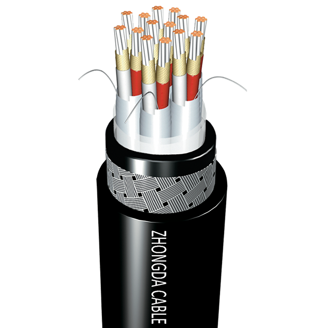
For maximum protection against internal crosstalk, high-quality marine cables utilize an individual Pair Screen. In this construction, every single twisted pair within a multi-pair cable is individually wrapped in aluminum and polyester tape. This creates a dedicated Faraday cage around each specific sensor circuit. It completely stops the signal of one pair from leaking out and prevents adjacent signals from bleeding in. This isolation is an absolute requirement for tightly packed analog sensor loops.
Shielding Type | Construction Detail | Primary Defense Target | Best Application Scenario |
|---|---|---|---|
Pair Screen | Individual aluminum foil wrap around each twisted pair. | Internal crosstalk and adjacent wire signal bleed. | Multi-core cables carrying multiple analog 4-20mA sensor loops. |
Overall Screen | Outer aluminum foil backed by a tinned copper wire braid. | External electromagnetic and radio frequency interference. | Cables routed near radar arrays or heavy propulsion motors. |
While individual screens manage internal crosstalk, an overall shield is necessary to protect the entire cable assembly from external interference. After all the individually screened pairs are bundled together, an overall layer of aluminum foil backed by a tinned copper wire braid is applied. The foil provides total coverage against high-frequency radar waves. Meanwhile, the dense copper braid provides structural integrity and excellent defense against low-frequency machinery noise.
Even the most robust systems occasionally experience issues. When sensor readings become erratic, marine electricians must execute a systematic troubleshooting process rather than relying on guesswork.
Identifying attenuation is usually the first step. On large commercial vessels, cable runs can extend for hundreds of meters. If a 24-volt signal leaves the control room but arrives at the remote sensor as 18 volts, severe attenuation is occurring. Technicians use digital multimeters to measure loop resistance and compare it against original manufacturer specifications. A sudden spike in resistance strongly indicates physical crushing, micro-fractures, or severe localized corrosion.
Ground loops are another frequent culprit that introduce a low-frequency hum into data lines. This occurs when a cable shield is incorrectly grounded at both ends, such as at the sensor and at the main panel. If those two locations possess slightly different voltage potentials, an unwanted electrical current is forced to flow through the shield itself. This induces noise into the internal data wires. The standard maritime solution is to ensure the shield is grounded at one end only. Typically, this is done at the main control panel, allowing it to drain interference without creating a conductive loop.
To find hidden damage without tearing apart bulkheads, technicians rely on Time Domain Reflectometers. This tool sends a short electrical pulse down the wire and measures the time it takes for the reflection to return. By analyzing this reflected wave, the tool can pinpoint the exact location in meters of a crushed cable, a severed conductor, or a section heavily saturated with saltwater. This precise diagnostic capability saves crews hours of manual labor.
Selecting the correct infrastructure during the engineering phase is the most effective way to prevent future signal degradation. Procurement teams must evaluate several strict criteria before approving materials for shipboard use. Do not settle for generic industrial wire.
The maritime industry is heavily regulated. Any installed cable must be type-approved by recognized international classification societies. Certifications from the American Bureau of Shipping, Det Norske Veritas, or Lloyds Register guarantee that the product has survived rigorous third-party testing for flame retardance, extreme temperature tolerance, and mechanical endurance.
Material selection is equally critical. Because bare copper oxidizes rapidly in salt-heavy air, marine cables must strictly utilize tinned copper conductors. Each individual strand is coated to prevent corrosion. For mechanical defense, Galvanized Steel Wire Braid is highly effective at preventing physical crushing in high-traffic areas. Bronze Wire Braid is often utilized on weather decks where non-magnetic properties are required. Additionally, prioritize outer sheaths made from SHF1 or SHF2 halogen-free, mud-resistant compounds. These advanced jackets, standard in ZDCables product lines, prevent toxic gas emissions during a fire while resisting harsh drilling muds on offshore platforms.
Procuring top-tier materials only solves half the equation. Proper installation and proactive maintenance dictate the ultimate lifespan of the system. The most common cause of immediate signal failure is improper handling during installation. Every cable has a specified minimum bend radius. If a technician bends a cable too sharply around a tight bulkhead corner, the internal foil screen will tear. Once ruptured, its ability to block interference is permanently compromised.
Installation crews must strictly separate high-voltage power lines from low-voltage data lines. Running a sensitive sensor wire in the same tray as a massive propulsion cable guarantees severe data corruption. They must be routed in separate conduits. If intersection is unavoidable, they should cross only at strict 90-degree angles.
Preventative maintenance requires regular visual audits. Crews should walk the cable trays monthly. They must look for cracking or blistering of the outer jacket, green powdery residue at termination points indicating galvanic corrosion, or physical pinching where cables pass through watertight transit seals. If diagnostic testing reveals water has migrated several meters into the core, repair is no longer an option. The compromised section must be replaced immediately.
The financial and operational cost of poor quality in maritime environments is exceptionally high. Purchasing cheap uncertified wire may save a fraction of the budget upfront. However, it inevitably leads to expensive system downtime, complex troubleshooting at sea, and severe safety risks. When a dynamic positioning sensor fails during a critical offshore maneuver due to a degraded connection, the consequences can be catastrophic.
Choosing the right supplier is a strategic operational decision. Shipbuilders and operators must partner with manufacturers who deeply understand marine specifications and the physics of signal preservation. A reputable supplier will provide full transparency regarding their materials, offer comprehensive testing documentation, and supply robust fire-resistant solutions tailored to your specific vessel class. By prioritizing engineering quality and consulting with experts to select the proper Instrumentation Cable, operators can ensure their vital data networks remain accurate, secure, and fully operational.
Marine environments are notoriously unforgiving to electrical systems. Heavy machinery noise, high-frequency radar, and the corrosive nature of the ocean constantly threaten to disrupt critical shipboard operations. By understanding these threats and investing in proper shielded construction, operators can effectively neutralize signal degradation.
Implementing strict separation during installation, conducting routine diagnostic tests, and utilizing advanced shielding techniques are proven strategies for maintaining data integrity. Audit your current marine cable setups today. Consult with maritime infrastructure experts and upgrade your vessel network with certified ZDCables solutions to ensure safe, uninterrupted voyages for years to come.
A marine instrumentation cable is specifically engineered with tinned copper conductors to resist corrosion, specialized marine-grade jacketing that is often halogen-free and mud-resistant, and heavy-duty metallic armoring to withstand saltwater, constant vibration, and strict maritime safety standards. Standard industrial cables lack these defenses and will quickly degrade in harsh offshore conditions.
A pair screen involves wrapping each individual twisted pair of wires in a highly conductive metallic foil. This creates a localized Faraday cage around that specific pair. It prevents its internal electrical signal from leaking out while simultaneously stopping external signals from bleeding in from adjacent wires.
Yes. If the outer protective jacket is damaged by abrasion or UV exposure, saltwater or atmospheric moisture will seep into the cable core. This moisture alters the electrical capacitance between the internal wires, leading to severe signal attenuation. Eventually, it causes the copper conductors to oxidize and corrode, resulting in complete signal failure.
Power cables carry high voltages and massive currents, which naturally generate strong expansive electromagnetic fields. If an instrumentation cable is laid too close to a power cable, this magnetic field will cause electromagnetic interference. This induces unwanted voltages and corrupts the highly sensitive low-voltage data signals.
In maritime applications, this refers to prioritizing fire-resistant and flame-retardant properties when selecting infrastructure. In the event of a shipboard fire, these specialized fire-survival cables are designed to continue transmitting critical signals for a specified duration. This ensures emergency lighting controls, fire-suppression commands, and evacuation alarms remain active, allowing for safe crew response.
Technicians typically use a digital multimeter to measure the loop resistance and compare it against the original baseline specifications. For more advanced diagnostics, a Time Domain Reflectometer is used to send an electrical pulse down the wire. The reflected wave can pinpoint the exact physical location of water ingress, crushing, or a severed conductor.
The maximum run length depends largely on the wire gauge, the specific voltage of the power supply, and the minimum voltage required by the receiving instrument. Generally, using high-quality marine cables with proper cross-sections, 4-20mA signals can travel several thousand meters without significant data loss, provided the shielding is intact and loop resistance remains within the transmitter limits.
 简体中文


