

Views: 0 Author: Site Editor Publish Time: 2026-08-19 Origin: Site


Misapplying cable types in industrial environments introduces severe engineering risks. Incorrect specification directly leads to catastrophic equipment failure, signal degradation, and severe safety hazards. Engineers and procurement teams face a constant challenge on the job site. You must design electrical systems requiring both heavy energy transmission and precise automated signaling. These systems often operate in constrained physical spaces, wet trenches, or high-vibration factory floors. Relying on guesswork or outdated specs will shut down a production line. You must evaluate cables based on strict technical parameters. Voltage rating, conductor cross-section, shielding, and broader classification categories dictate your choice. Understanding these factors ensures the correct deployment of a Power Cable versus a Control Cable. We will break down the exact engineering differences so you can specify the right materials for your next build.
Primary Function: A power cable is engineered to transmit high-level electrical energy from a source to equipment (falling under energy distribution categories), whereas a control cable is designed to transmit low-voltage signals to control, monitor, and automate processes (classified as electrical equipment cables).
Voltage Ratings: Power cables operate at high voltage classes (typically 0.6kV up to high-voltage transmission levels), while control cables are restricted to low-voltage applications (commonly 300V to 600V).
Physical Construction: Power cables utilize larger conductor cross-sections to handle high currents and heat dissipation; control cables use smaller, often highly flexible, multi-core conductors optimized for routing and signal integrity.
Interference Management: Control cables require specialized shielding (such as copper braid or aluminum foil) to protect sensitive signals from Electromagnetic Interference (EMI), a factor less critical for raw power transmission.
A Power Cable serves as the primary artery for electrical energy in any facility. Manufacturers engineer these heavy-duty lines to handle massive electrical loads safely over long periods. They feature thick insulation layers, typically made from Cross-Linked Polyethylene (XLPE) or heavy-duty Polyvinyl Chloride (PVC). This thick dielectric barrier prevents high-voltage arcing, electrical leakage, and phase-to-phase shorts. The outer sheathing provides robust mechanical protection against physical impacts, moisture ingress, and chemical exposure on the factory floor.
Conductors inside these cables use large-gauge copper or aluminum. Aluminum offers a distinct weight advantage for overhead lines and long-distance utility runs, while copper provides superior conductivity for compact routing inside switchgear and motor control centers. Thermal dynamics dictate their physical size. Continuous high-current transmission generates significant heat due to I²R losses (current squared times resistance). The cable must dissipate this heat into the surrounding environment to prevent the insulation from melting. Engineers calculate ampacity ratings based on the cable's ability to maintain safe operating temperatures under full load, factoring in ambient temperature and conduit fill limits.
Industrial facilities rely on heavy energy lines for their most demanding applications. Primary use cases include main utility feeds connecting step-down transformers to facility switchgear. They supply raw energy to heavy machinery, large motor drives, industrial heaters, and extensive plant-wide distribution networks. The installation environment directly dictates the specific physical construction of the jacket and armor.
Overhead transmission lines demand high tensile strength to survive wind and ice loading. They often incorporate steel cores (ACSR) and require exceptional UV resistance to withstand constant sunlight degradation. Underground installations face entirely different threats. Direct burial lines require heavy steel wire armoring (SWA) or steel tape armoring (STA) to resist crushing forces from soil settlement and heavy vehicle traffic above. Underground variants also utilize specialized water-blocking tapes and moisture barriers to prevent water ingress, which causes dielectric failure and "treeing" in the insulation over time.
Specialized subsets exist within this category. Motor cables function primarily to deliver energy, but they possess unique traits. When paired with Variable Frequency Drives (VFDs), these cables require specific flexibility for routing. They also incorporate specialized heavy copper shielding to contain the high-frequency electrical noise generated by the drive's switching components, preventing it from interfering with nearby sensitive equipment.
Common Insulation Materials for Energy Transmission
Material Type | Max Operating Temp | Primary Advantage | Typical Application |
|---|---|---|---|
PVC (Polyvinyl Chloride) | 70°C to 90°C | Cost-effective, highly flame retardant | Indoor low-voltage distribution |
XLPE (Cross-Linked Polyethylene) | 90°C | Excellent moisture resistance, high thermal capacity | Underground and medium-voltage networks |
EPR (Ethylene Propylene Rubber) | 90°C to 105°C | Superior flexibility in cold weather | Heavy industrial and mining operations |
A Control Cable prioritizes data, logic, and signal transmission over raw energy delivery. These cables feature a multi-core construction, sometimes containing up to 60 individual conductors in a single jacket. They utilize small-gauge conductors (typically ranging from 18 AWG to 12 AWG, or 0.75mm² to 2.5mm²) because the amperage required to send a digital or analog signal is minimal. Manufacturers classify them strictly as "electrical equipment cables" rather than utility or distribution lines.
Flexibility stands as a primary engineering requirement. Signal lines use a high strand count within each core, often utilizing Class 5 or Class 6 fine copper stranding. This fine stranding allows the cable to bend easily without snapping the internal metal. This flexibility proves essential when routing through complex control panels, narrow cable tracks, and moving automated machinery. Stiff, solid-core cables would work-harden and fail quickly under continuous mechanical stress.
Modern automation depends entirely on reliable signal transmission. Signal lines connect Programmable Logic Controllers (PLCs) to various field devices across the plant floor. They link relays, proximity sensors, temperature probes, limit switches, and robotic actuators back to the central processing unit. The entire manufacturing process halts if these signals fail, degrade, or experience interference.
Signal fidelity remains the top priority. Industrial environments subject these lines to constant flexing, vibration, and mechanical shock. The internal construction must prevent conductor breakage. Even a momentary loss of continuity can cause a robotic arm to misalign, a safety interlock to fail, or a batch process to ruin thousands of gallons of product. Engineers select highly flexible, durable jackets like Polyurethane (PUR) or Thermoplastic Elastomer (TPE) for applications involving continuous movement, such as drag chains on CNC machines.
Common Failure Points in Factory Signal Routing
Conductor Fatigue: Using stiff Class 2 stranded wire in dynamic drag chains causes the copper to snap after repeated bending cycles.
Jacket Degradation: Standard PVC jackets harden, crack, and fail when exposed to synthetic machine oils or hydraulic fluids.
Capacitance Distortion: Running excessively long unshielded lines causes high capacitance, which rounds off the edges of 24VDC square wave signals, leading to missed PLC counts.
Crush Damage: Routing unarmored signal lines across forklift traffic zones without proper floor conduit results in immediate physical destruction.
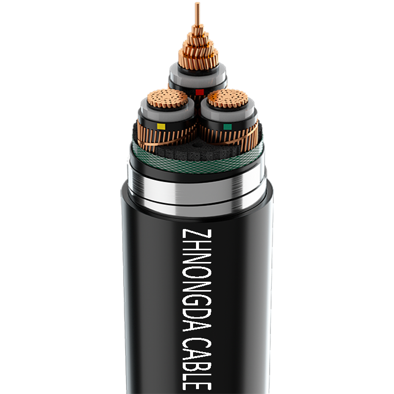
Voltage classes clearly separate these two categories. Energy transmission lines operate at high voltage levels to push massive amounts of current. Standard low-voltage distribution starts at 0.6/1kV. Medium and high-voltage transmission lines scale up to 15kV, 33kV, 132kV, and beyond. This high voltage allows efficient energy transfer over long distances with minimal power loss, requiring thick, highly engineered dielectric materials to prevent catastrophic phase-to-ground faults.
Signal lines handle much lower potentials. Standard ratings fall between 300/500V or 600V. These low voltages easily carry 4-20mA analog signals from pressure transmitters or 24V DC digital commands to solenoid valves. The voltage requirements directly dictate the thickness and material of the dielectric insulation. Energy lines need thick, high-grade insulation to contain thousands of volts. Signal lines require only thin insulation layers, keeping their overall diameter small, manageable, and easy to terminate in high-density terminal blocks.
Conductor sizing reveals the intended function of the installation. Energy transmission requires large cross-sectional areas. Thick conductors minimize electrical resistance. Low resistance prevents excessive voltage drop over long runs. It also prevents the line from overheating when carrying hundreds of amps to a heavy industrial motor. You will commonly see sizes like 4/0 AWG, 250 kcmil, or 500 kcmil (120mm² to 240mm²) in these applications.
Signal lines require minimal cross-sectional area. The current loads for signaling are negligible, often measuring in milliamps. Using large conductors for control signals wastes expensive copper and makes the line impossibly stiff to route. Engineers specify wire gauges just large enough to maintain physical integrity during pulling and to overcome minor resistance over the required distance. Common sizes are 18 AWG or 16 AWG (0.75mm² or 1.5mm²).
Industrial environments generate massive amounts of electrical noise. Large motors, arc welders, and VFDs create severe Electromagnetic Interference (EMI). Signal lines rely heavily on specialized shielding to prevent this noise from corrupting sensitive data. Manufacturers use tinned copper braids or aluminum foil wraps around the conductor cores. Aluminum foil provides 100% coverage against high-frequency noise but is physically fragile. Tinned copper braid provides 85-95% coverage, handles low-frequency noise better, and adds mechanical strength. This shield intercepts external EMI and shunts it to ground via a drain wire, preserving signal integrity.
Standard energy lines typically lack EMI shielding. The massive voltage and current they carry remain largely unaffected by external electrical noise. A 480V, 200A motor feed will not notice a few millivolts of induced noise. However, exceptions exist. Lines connecting VFDs to servo motors require heavy shielding. In this specific case, the energy line generates the EMI, and the shield prevents that noise from radiating outward into the facility and disrupting nearby PLCs.
Industry standards mandate specific color coding conventions. This allows technicians to visually distinguish circuits quickly within a crowded tray or panel. Signal lines frequently utilize black cores with printed white numbers (e.g., 1 through 50). This numbering system allows easy identification of dozens of individual cores within a single multi-core jacket. Some signal lines use solid colors based on specific standards like DIN 47100 for data transmission.
Energy lines rely on standardized phase colors. Depending on the regional electrical code (such as NEC in the US or IEC in Europe), you will see specific combinations. Common phase colors include brown, black, grey, and blue for phases and neutral in IEC regions, or black, red, blue, and white in NEC regions. A green/yellow striped core universally designates the protective earth ground. These visual cues prevent dangerous phase-to-phase wiring errors during installation and maintenance.
Technical Comparison: Energy vs. Signal Lines
Technical Parameter | Power Cable | Control Cable |
|---|---|---|
Primary Function | High-level energy transmission | Low-voltage signal and data routing |
Voltage Rating | 0.6/1kV up to high-voltage transmission | Typically 300V to 600V |
Conductor Size | Large cross-section (low resistance) | Small cross-section (high flexibility) |
EMI Shielding | Rare (except for VFD/motor applications) | Standard (foil or braided copper) |
Core Identification | Standard phase colors (Brown, Black, Grey) | Numbered black cores or specific solid colors |
Selecting the right materials requires a rigorous evaluation of the installation environment. You must determine if the routing is static or dynamic. Static installations, where the line sits in a tray and never moves, allow for stiffer constructions with standard PVC jackets. Dynamic applications, like robotic arms or automated gantry cranes, demand highly flexible constructions with specialized jackets that withstand millions of bending cycles without fatiguing the copper.
Evaluate chemical exposure carefully. Factory floors often expose routing paths to machine oils, hydraulic fluids, and harsh cleaning solvents. Standard PVC degrades rapidly in these conditions. Specify oil-resistant jackets like PUR or specialized elastomers. Temperature extremes also dictate material choice. High-heat environments near furnaces require silicone or Teflon insulation. Finally, calculate the required bend radii. Forcing a thick line past its minimum bend radius causes internal conductor fatigue, micro-cracking in the insulation, and premature failure.
Electrical codes govern industrial installations strictly. You must verify certifications specific to your region and application. Common standards include the National Electrical Code (NEC) in North America, and International Electrotechnical Commission (IEC) standards globally. Look for specific testing marks like UL (Underwriters Laboratories) or CE (Conformité Européenne). For example, NEC Article 336 covers Power and Control Tray Cable (TC), while Article 725 covers remote-control and signaling circuits.
Substituting types against code mandates introduces massive compliance risks. Using a non-rated jacket in a plenum space violates fire safety codes, as it can spread toxic smoke through HVAC systems. Failing to use appropriately armored lines in hazardous, explosive environments (Class 1, Div 1) invites catastrophic accidents. Always match the specification directly to the regulatory requirement of the physical space. Using a TC-ER (Tray Cable - Exposed Run) rated line can save significant labor by eliminating the need for conduit between the tray and the equipment, provided it meets crush resistance standards.
Procurement teams must balance upfront costs against long-term reliability. Over-specifying wastes capital. Using a massive, heavily armored energy line where a lighter variant suffices increases copper costs unnecessarily. It also increases installation difficulty due to extreme stiffness, driving up labor hours as electricians struggle to bend it into panels.
Under-specifying carries far worse consequences. Choosing a cheaper, unshielded signal line for a noisy factory floor leads to constant data errors, erratic machine behavior, and massive downtime. Selecting a jacket material that degrades under UV light causes premature failure on outdoor rooftop installations. The lifecycle value of correctly specified materials far outweighs the initial purchase price. Factor in the costs of potential downtime, replacement labor, and safety hazards when making procurement decisions.
Installers frequently make the error of running energy and signal lines in the same conduit or cable tray. This practice invites severe operational problems. High-current lines generate strong electromagnetic fields. When placed too close to signal lines, these fields induce unwanted voltages into the low-voltage wires. This cross-talk corrupts data, causes false sensor readings, and triggers erratic machine behavior that is notoriously difficult to troubleshoot.
Mitigate this risk through strict physical separation. Electrical codes dictate specific minimum distances between energy and signal routing. If they must cross paths, ensure they intersect at a strict 90-degree perpendicular angle to minimize magnetic field coupling. When sharing a tray is absolutely unavoidable due to space constraints, install grounded metallic dividers to create a physical Faraday cage between the high-voltage and low-voltage lines.
Connection points represent the most vulnerable parts of any electrical system. Improper termination of a Control Cable shield ruins its effectiveness. You must ground the shield correctly, typically at one end only (usually at the control cabinet), to prevent ground loops. Ground loops occur when both ends are grounded at slightly different voltage potentials. This allows stray currents to travel down the shield, introducing the exact electrical noise you intended to block.
Energy line terminations require precise mechanical execution. Inadequate lug sizing or improper crimping pressure creates high-resistance joints. These loose connections generate intense localized heat under heavy loads. Over time, this thermal stress melts insulation, oxidizes the copper, and frequently causes electrical panel fires. Always use calibrated crimping tools, apply anti-oxidation compound on aluminum conductors, and follow manufacturer torque specifications for mechanical lugs.
The choice between energy transmission and signal routing is strictly dictated by the application's electrical load, the operating environment, and standard classifications. Energy lines deliver raw power through large conductors and thick insulation. Signal lines route sensitive low-voltage data through flexible, shielded, multi-core structures. Mixing their applications compromises safety, violates electrical codes, and destroys system integrity.
Take immediate action to secure your installation by following these steps:
Verify the exact voltage requirements and calculate the necessary ampacity to select the appropriate conductor size.
Assess the installation environment for EMI risks, chemical exposure, and dynamic movement to determine shielding and jacket needs.
Consult detailed manufacturer specification sheets to ensure the selected materials meet UL, CE, or NEC ratings for your specific application.
Perform a site-specific routing audit to ensure proper physical separation between high-voltage and low-voltage trays.
Engage with a certified electrical engineer to review and finalize your bill of materials before issuing purchase orders.
A: While physically possible to transmit a signal through a large wire, it is highly inefficient. Large conductors lack necessary EMI shielding to protect data. They are difficult to route through tight control panels. Using them for low-voltage signals often violates electrical codes and wastes valuable space and materials.
A: Most standard signal lines are rated for 300V to 600V. This depends on the specific manufacturing standard and insulation thickness. In contrast, energy transmission lines start at 600V and scale up to hundreds of thousands of volts for utility transmission.
A: A motor cable is a specific type of energy line designed to deliver heavy current to motors. They often feature heavy shielding for use with Variable Frequency Drives (VFDs). A signal line only handles the low-voltage command signals and cannot carry the current required to spin a large motor.
A: Low-voltage signals are highly susceptible to electromagnetic interference (EMI). Nearby heavy machinery, welders, or high-voltage lines generate electrical noise. Shielding intercepts this noise and grounds it. Without shielding, EMI corrupts data packets and causes severe automation errors.
A: You can identify them through several visual cues. Energy lines have a larger overall diameter and thicker internal conductors. Signal lines are highly flexible with many small-gauge wires. Signal cores often use black insulation with printed white numbers, while energy lines use standard solid phase colors.
A: Electrical codes generally prohibit or heavily restrict this practice. Running them together creates a high risk of induced voltage and EMI cross-talk. Safe installation requires specific physical separation distances or the use of grounded, shielded metallic dividers within cable trays.
 简体中文
简体中文 

