

Views: 0 Author: Site Editor Publish Time: 2026-09-13 Origin: Site


The rapid transition toward semi-autonomous and fully automated maritime operations fundamentally changes vessel engineering. Sophisticated software now manages propulsion, navigation, and safety systems. However, this software remains entirely dependent on the reliability of the physical layer. In harsh marine environments, signal latency, data loss, or physical degradation present severe operational risks. Saltwater ingress, extreme engine vibration, and electromagnetic interference constantly threaten data integrity. Selecting the correct control cable is never a commodity purchasing decision. It represents a foundational engineering requirement. Proper specification ensures continuous, fail-safe ship automation. You must prioritize signal integrity and environmental resilience to maintain maritime operations. This guide details the technical specifications, compliance standards, and installation practices required to build a robust shipboard automation network.
Signal Integrity is Mission-Critical: Automation systems require uninterrupted data flow; proper EMI/RFI shielding in control cables prevents catastrophic system miscommunications, especially near heavy machinery.
Protocol Compatibility is Non-Negotiable: Modern marine automation cables must meet the strict electrical characteristics required by advanced maritime networks (e.g., NMEA 2000, CAN bus, PROFINET).
Compliance Dictates Viability: Cables must meet stringent international maritime classification standards (e.g., DNV, ABS, Lloyd’s Register) to ensure safety and insurance compliance.
Environmental Resilience Extends Lifecycle: Specifying Low Smoke Zero Halogen (LSZH), mud-resistant, and water-blocked materials prevents rapid degradation and protects crew during emergencies.
Modern shipboard automation relies on a highly distributed architecture. Systems like propulsion control, ballast management, and dynamic positioning require constant data exchange across the entire length of the vessel. Peripheral sensors monitor temperature, pressure, and fluid levels continuously in real time. They send this raw data back to the central Integrated Platform Management System (IPMS). The Marine Control Cable serves as the critical physical bridge in this network. It transmits low-voltage signals between field devices and central processing units. Flawless transmission prevents catastrophic equipment failures and ensures the vessel operates within safe parameters.
Compatibility with modern marine communication protocols is mandatory for these physical links. Advanced networks utilize NMEA 2000, CAN bus, and Modbus frameworks to standardize communication between disparate pieces of equipment. These protocols demand specific electrical characteristics to function correctly. A mismatched cable alters signal impedance, causing data packet loss and network collisions. You must ensure the physical cable aligns perfectly with the chosen network protocol. Seamless, error-free integration allows the IPMS to make real-time, automated decisions safely without waiting for re-transmitted data packets.
Evaluating cable performance requires strict baseline metrics tailored to the maritime environment. Minimal voltage drop is essential for long cable runs across large commercial vessels, where a sensor might be located hundreds of meters from the control room. Precise impedance matching prevents signal reflection and data corruption at the termination points. High flexibility simplifies routing through congested shipboard bulkheads and tight cable trays. Resistance to mechanical stress ensures longevity in high-vibration environments near the main engines. These criteria define the baseline for acceptable operational performance.
Real-time automation environments possess zero tolerance for signal latency. Dynamic positioning systems adjust thrusters in milliseconds to maintain vessel heading against strong ocean currents. Delayed signals cause overcorrection, mechanical strain on the thrusters, and deviation from the intended coordinates. The physical cable must support high-speed data transmission without bottlenecking the network. Success means the automation system operates with absolute synchronization, regardless of external environmental factors or heavy machinery operating nearby.
Performance Metric | Technical Requirement | Operational Impact on Ship Automation |
|---|---|---|
Voltage Drop | Must remain below 3% for critical circuits. | Ensures remote sensors receive adequate power and return accurate analog signals. |
Impedance Matching | Typically 120 ohms for CAN bus networks. | Prevents signal reflection, eliminating data packet loss and network collisions. |
Flexibility | Class 5 stranded conductors. | Allows tight bending radii during installation in cramped engine room trays. |
Latency Threshold | Sub-millisecond transmission delay. | Enables real-time dynamic positioning and emergency shutdown sequencing. |
Marine environments accelerate the corrosion of standard metals at an alarming rate. Bare copper oxidizes rapidly when exposed to high-humidity, salt-laden air common on weather decks and in poorly ventilated compartments. This oxidation increases electrical resistance, generates heat, and degrades signal quality over time. Tinned copper conductors provide superior corrosion resistance for maritime applications. A microscopic layer of tin protects the underlying copper from atmospheric degradation and galvanic corrosion. You should specify tinned copper for all critical automation circuits to maintain long-term signal integrity.
Stranding classes directly impact cable flexibility and vibration tolerance. Solid conductors fracture easily under the continuous, low-frequency vibration generated by two-stroke marine diesel engines. Class 2 stranded conductors offer basic flexibility for fixed installations in relatively stable areas of the ship. Class 5 flexible stranding provides superior resistance to mechanical fatigue. High-vibration zones require Class 5 conductors to prevent work-hardening and sudden circuit failure. Proper stranding selection extends the operational lifespan of the installation and prevents intermittent signal drops.
Thermal stability is a primary concern in confined shipboard spaces. Engine rooms and thruster compartments generate extreme ambient heat during normal operations. Standard PVC insulation degrades, becomes brittle, and melts under these conditions. Cross-linked polyethylene (XLPE) and ethylene propylene rubber (EPR) provide superior thermal resistance. These materials maintain their dielectric properties even at elevated operating temperatures up to 90°C. They prevent short circuits caused by insulation breakdown and ensure the automation signals remain isolated.
Safety mandates strictly regulate outer sheath materials on all commercial and passenger vessels. Traditional halogenated plastics release toxic, corrosive gases during a fire. These gases blind crew members, damage respiratory systems, and destroy sensitive electronic circuit boards. Low Smoke Zero Halogen (LSZH) sheaths are a strict safety requirement. LSZH materials emit minimal smoke and zero toxic halogens when burned. They protect human life, maintain visibility for evacuation, and preserve critical equipment during shipboard emergencies.
Water ingress destroys automation networks from the inside out. If an outer sheath breaches on a weather deck due to mechanical impact, capillary action draws water inward along the conductors. Water-blocking tapes and swellable yarns provide longitudinal water tightness. When exposed to moisture, these materials expand instantly. They form an impenetrable gel barrier that stops water migration dead in its tracks. This technology isolates the damage to the immediate area and protects the broader automation system from catastrophic short circuits.
Shipboard environments feature a dense concentration of electronic equipment operating in confined spaces. Radars, high-frequency radios, and heavy machinery operate in close proximity to sensitive control networks. This density creates severe electromagnetic interference (EMI) risks. Unshielded cables act as antennas, absorbing this ambient noise from the surrounding environment. EMI corrupts low-voltage automation signals, causing erratic system behavior and false sensor readings. Robust shielding is necessary to maintain data integrity across the vessel.
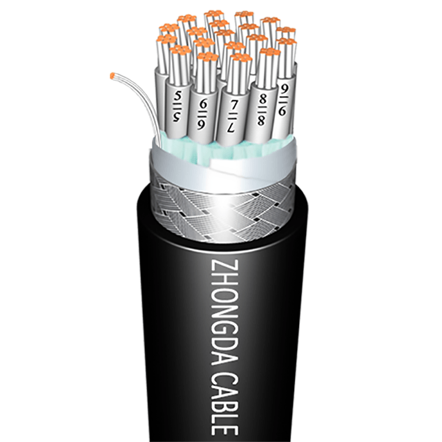
Variable Frequency Drives (VFDs) and heavy propulsion systems generate significant harmonic noise that easily penetrates standard data cables. A high-quality Marine Automation Cable utilizes specific shielding strategies to combat this interference. Individual pair shielding uses aluminum/polyester tape around each twisted pair to prevent cross-talk between adjacent circuits within the same cable. Overall shielding, using dense tinned copper braiding, blocks external EMI from penetrating the cable core. Complex automation networks often require both methods simultaneously for complete protection in high-noise environments.
Engineers often confuse EMI shielding with mechanical armoring, but they serve entirely different purposes. Shielding protects the electrical signal from invisible interference. Armoring protects the physical cable structure from blunt force trauma and abrasion. Galvanized Steel Wire Braid (GSWB) and Bronze Wire Braid offer high-level mechanical defense. They absorb physical impacts, resist abrasive wear against steel bulkheads, and provide a secondary layer of grounding. Armoring prevents catastrophic cable failure in harsh industrial zones.
Certain shipboard areas strictly require armored cables to survive the operational environment. Exposed cargo holds experience heavy equipment traffic, swinging crane loads, and falling debris. Weather decks face extreme wave impacts, ice formation, and constant foot traffic. Hidden cable trays often harbor rodents that chew through standard polymer sheathing. In these high-risk zones, armoring provides the necessary crush and impact resistance. It guarantees the physical survival of the automation link under the most punishing conditions.
Maritime operations are heavily regulated by international classification societies to ensure baseline safety and reliability. Bodies like DNV, the American Bureau of Shipping (ABS), and Lloyd’s Register set strict engineering standards for all vessel components. They mandate rigorous approval processes for shipboard cables. Cables undergo extreme testing for fire resistance, cold bending at sub-zero temperatures, and chemical exposure. Type Approval from these societies verifies that a cable meets global safety benchmarks and is fit for maritime use.
Lacking proper certification severely impacts vessel operations and legal standing. Port state control inspectors routinely check component compliance during random vessel audits. Uncertified cables can halt vessel commissioning, delay departures, and result in heavy fines. Furthermore, insurance providers require strict adherence to classification rules. Using non-approved cables voids maritime insurance policies, exposing operators to massive liability in the event of a fire or system failure. You must verify all classification approvals before finalizing any procurement decisions.
The International Electrotechnical Commission (IEC) defines the baseline safety standards for marine cables. Compliance with these specific metrics is non-negotiable for passenger ferries, oil tankers, and commercial cargo vessels. The standards focus heavily on how the cable behaves during a fire, as shipboard fires are among the most dangerous maritime emergencies.
IEC 60332: Defines flame retardance. It ensures the cable self-extinguishes and does not propagate a fire along the length of a cable tray.
IEC 60754: Regulates halogen gas emissions. It verifies the cable materials are entirely halogen-free, preventing the release of toxic chlorine or fluorine gas.
IEC 61034: Measures smoke density. It guarantees visibility remains high during a fire scenario, allowing crew members to find escape routes.
Critical emergency automation systems require even higher protection than standard flame retardance. Fire pumps, emergency lighting, and emergency shutdown systems must operate continuously during an active blaze. IEC 60331 defines the requirements for fire-resistant cables. These cables utilize specialized mica glass tapes wrapped directly over the copper conductors. They maintain circuit integrity for up to three hours in a direct fire at temperatures exceeding 750°C. This allows the crew to execute safe evacuation and fire suppression procedures without losing control of critical systems.
IEC Standard | Testing Focus | Operational Benefit During an Emergency |
|---|---|---|
IEC 60332 | Flame Retardance | Prevents fire from spreading rapidly along vertical and horizontal cable trays. |
IEC 60754 | Halogen Emission | Prevents release of toxic, corrosive gases that damage lungs and electronics. |
IEC 61034 | Smoke Density | Maintains clear visibility for safe crew evacuation and firefighting efforts. |
IEC 60331 | Fire Resistance | Maintains electrical circuit integrity during an active fire for up to 3 hours. |
Specifying commercial-grade cables in a marine environment guarantees rapid failure and severe operational headaches. Standard industrial cables cannot withstand constant saltwater exposure, UV radiation, and extreme vibration. The insulation cracks, conductors corrode, and signals drop intermittently. This leads to operational paralysis. A vessel stranded at sea or delayed in port due to automation failure incurs massive logistical penalties. The labor required to pull and replace degraded cables mid-ocean or during a tight dry-dock schedule is highly intensive and disruptive.
You must focus on a 20-to-30-year vessel lifecycle when designing the physical layer. High-grade marine cables prevent unplanned maintenance downtime. They endure the harsh environment without degrading, maintaining stable impedance and signal clarity year after year. This reliability keeps the vessel operational, on schedule, and out of the repair yard. Prioritizing robust physical infrastructure eliminates the cascading failures associated with cheap, non-compliant wiring.
Modern vessels contain hundreds of kilometers of cabling to support advanced automation, power, and communication networks. The cumulative weight of this infrastructure is massive and directly impacts vessel performance. Specifying advanced, thin-wall marine cables significantly reduces overall vessel weight. Advanced polymer chemistry allows for thinner insulation walls without sacrificing dielectric strength or mechanical toughness. Lighter vessels consume less fuel, achieve higher top speeds, and carry more profitable cargo. Weight optimization directly improves the hydrodynamic efficiency of the ship.
Optimized cable diameters also solve critical installation challenges during the shipbuilding phase. Shipboard cable trays are notoriously congested and space-restricted. Thick, inflexible cables are difficult to route through tight bulkheads and multi-cable transit (MCT) blocks. Thin-wall cables improve tray fill ratios. They allow engineers to install more circuits in the same physical space without violating heat dissipation rules. This flexibility accelerates the shipbuilding process, reduces installation labor, and simplifies future maintenance access.
Maritime automation technology evolves rapidly. Vessels built today will require new sensors, upgraded software, and additional control nodes in five years. Rewiring a commissioned vessel is highly disruptive, requiring bulkheads to be unsealed and interior paneling to be removed. You must design scalability into the initial cable infrastructure. Installing cables with excess data capacity prepares the vessel for future demands without requiring major overhauls.
Including "dark cores" (unused spare conductors) within the cable assembly is a proven strategy for future-proofing. When new automated systems are added, engineers simply connect the new devices to the existing dark cores already routed through the ship. This eliminates the need to pull entirely new cables through sealed bulkheads and fire-stops. Scalable infrastructure protects the vessel against rapid technological obsolescence and ensures it can adapt to new maritime regulations.
Engine rooms and thruster compartments represent high-risk installation areas for any physical infrastructure. The constant mechanical vibration fatigues copper conductors over time, leading to micro-fractures. Improper routing accelerates this degradation. You must manage the cable bend radius strictly during installation. Bending a cable beyond its specified limit stresses the insulation, fractures the internal shielding, and alters the electrical characteristics. Always adhere to the manufacturer's minimum bend radius guidelines, typically 6 to 8 times the outer diameter of the cable.
Mitigation tactics require careful physical planning and execution. Use vibration-damping transit frames where cables pass through steel bulkheads. These frames absorb mechanical shock and prevent the steel edges from abrading the cable sheath. Avoid overtensioning cables during the pulling process. Excessive pulling force stretches the copper, reduces the cross-sectional area, and alters the electrical impedance. Finally, enforce strict physical segregation between high-voltage power cables and low-voltage control cables. Separation prevents inductive cross-talk from corrupting sensitive automation data.
Marine cables face continuous exposure to severe environmental hazards that destroy standard plastics. Weather decks subject cables to intense UV radiation, extreme temperature swings, and constant saltwater spray. UV light degrades standard polymers, causing them to crack, peel, and expose the inner cores. Engine rooms expose cables to hydraulic fluids, synthetic lubricants, and high ambient temperatures. Offshore support vessels (OSVs) and oil tankers face the added threat of highly corrosive drilling muds and aggressive chemicals.
You must match the sheath compound to the specific environmental threat present in each zone of the ship. Standard LSZH (SHF1) is suitable for general interior spaces like accommodation blocks and control rooms. However, harsh chemical zones require cross-linked elastomer sheaths (SHF2). SHF2 compounds offer enhanced resistance to oils, muds, and extreme temperature fluctuations. Selecting the correct outer sheath prevents premature environmental degradation and ensures continuous automation uptime.
Never assume a newly installed cable is flawless. Installation stress, accidental impacts, or improper termination can cause hidden internal damage. Mandatory pre-commissioning tests verify the physical and electrical integrity of the network before the automation system goes live.
Visual Inspection: Check all outer sheaths for abrasions, cuts, or severe kinks caused during the cable pull.
Continuity Testing: Verify that all conductors are properly terminated, unbroken, and connected to the correct pins.
Insulation Resistance (IR) Testing: Apply a high voltage to confirm the dielectric strength of the insulation. This detects microscopic tears or moisture ingress that could cause future short circuits.
Time Domain Reflectometry (TDR): Send a pulse down the cable to measure reflections. This pinpoints the exact location of impedance mismatches, crushed sections, or water ingress.
Documenting these baseline metrics allows engineers to track cable health over the vessel's lifespan. If a sensor fails five years later, maintenance teams can compare current TDR readings against the baseline to determine if the cable or the sensor is at fault.
Audit your current vessel automation schematics to identify critical control pathways and potential single points of failure in the physical layer.
Filter your cable procurement options strictly by classification society approvals (e.g., DNV, ABS) before evaluating other technical metrics.
Consult directly with certified marine cable manufacturers to match specific sheath compounds (SHF1 vs. SHF2) to your vessel's distinct environmental zones.
Request detailed technical data sheets to verify impedance matching and EMI shielding capabilities for your specific communication protocols.
Implement mandatory Time Domain Reflectometry (TDR) testing during commissioning to establish a baseline for future maintenance checks.
A: A standard control cable uses bare copper and standard PVC. A marine control cable utilizes tinned copper conductors to resist corrosion. It features Low Smoke Zero Halogen (LSZH) sheathing for fire safety. Furthermore, marine cables carry strict classification approvals (like DNV or ABS) and offer enhanced resistance to salt, oil, and extreme shipboard vibration.
A: Ships contain a high density of heavy machinery, Variable Frequency Drives (VFDs), and communication equipment. This creates intense electromagnetic interference. Unshielded cables absorb this noise, which corrupts low-voltage automation signals. Proper shielding blocks this interference, preventing erratic system behavior and catastrophic automation failures.
A: Shielding protects the electrical signal. It uses copper braids or aluminum tape to block electromagnetic interference (EMI) and maintain data integrity. Armoring protects the physical cable. It uses materials like galvanized steel or bronze wire braiding to provide physical defense against crushing, impacts, and severe abrasion.
A: SHF1 refers to a standard, halogen-free polymer sheathing suitable for general indoor marine environments. SHF2 indicates a robust, cross-linked elastomer compound. SHF2 offers superior resistance to harsh oils, drilling muds, and extreme temperature variations, making it ideal for engine rooms and offshore vessels.
A: Flame retardant cables (which prevent fire spread) are standard across the vessel. However, fire-resistant cables (which maintain circuit integrity during an active fire) are strictly required for critical safety systems. These include emergency fire pumps, lighting, and shutdown automation systems.
A: Continuous engine and wave vibration causes mechanical fatigue. Solid conductors will work-harden, become brittle, and eventually fracture under this stress. Marine cables must use stranded, flexible conductors (Class 2 or Class 5) to absorb mechanical movement and prevent sudden circuit disconnections.
A: Major maritime classification bodies include DNV, the American Bureau of Shipping (ABS), Lloyd's Register, Bureau Veritas (BV), and RINA. Securing Type Approval from these organizations ensures the cable meets rigorous international maritime safety, performance, and environmental standards.
 简体中文
简体中文 

