

Views: 0 Author: Site Editor Publish Time: 2026-08-16 Origin: Site


A Power Cable acts as the critical infrastructure bottleneck in commercial, industrial, and utility-scale electrical systems. It serves as the primary backbone connecting generation facilities directly to end-user equipment. We define an Electrical Power Cable as an engineered assembly of one or more conductors built specifically for bulk energy transfer. This explicitly distinguishes it from signal, control, or data lines designed for low-voltage information transmission. Mis-specifying these components introduces severe operational risks. Errors lead to excessive transmission loss, known as I²R losses, and accelerate thermal degradation. In worst-case scenarios, incorrect selection causes catastrophic failure and regulatory non-compliance. Understanding the exact physics of how a cable transmits electrical energy remains a prerequisite for success. Engineers must accurately evaluate conductor materials, insulation types, and voltage ratings to match specific project environments.
Transmission Efficiency: Electrical energy transmission relies on balancing voltage and current; specifying higher voltage cables for long distances exponentially reduces current, thereby minimizing heat generation and energy loss.
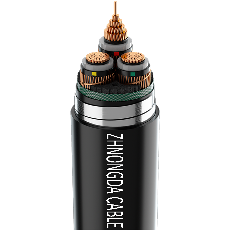
Component Synergy: A commercial-grade power cable is not just a wire; it is an engineered assembly where conductors, dielectric insulation, shielding, and armor work together to contain electromagnetic fields and resist environmental stress.
Specification Criteria: Selecting the correct electrical power cable requires evaluating ampacity requirements, installation environments (e.g., direct burial, subsea, conduit), and strict adherence to regional standards (NEC, IEC, IEEE).
Total Cost of Ownership: Upfront material costs (e.g., Copper vs. Aluminum) must be weighed against long-term operational efficiency, maintenance requirements, and the expected lifespan of the insulation material.
The conductor serves as the physical pathway for electron flow. It facilitates the movement of electrical energy from the source to the load. Engineers primarily choose between copper and aluminum for this core component based on specific site constraints and load requirements. Copper offers superior electrical conductivity, requiring a smaller cross-sectional area to carry the same current as aluminum. This makes copper ideal for space-constrained installations like underground duct banks or crowded cable trays. However, copper carries a heavier weight penalty and higher upfront material expense.
Aluminum provides a much lighter alternative. Utility companies heavily favor aluminum for large-scale distribution networks and overhead transmission lines. The lighter weight reduces mechanical strain on support structures and lowers pulling tension during installation. Aluminum does require a larger cross-section to match copper's ampacity, which means the overall cable diameter increases. Terminating aluminum also requires specific dual-rated lugs and oxide-inhibiting compounds to prevent galvanic corrosion and cold flow at the connection points.
Stranding configurations dictate mechanical performance and flexibility. Solid conductors offer simplicity but lack the flexibility needed for complex routing. Stranded conductors consist of multiple smaller wires twisted together. Class 2 rigid stranding is standard for fixed industrial installations, while Class 5 flexible stranding is used where tight bending radii are required. Stranding also helps mitigate the skin effect in alternating current systems. The skin effect pushes current toward the outer surface of the conductor at higher frequencies. For massive cross-sections exceeding 500mm², manufacturers use Milliken (segmental) conductors to force uniform current distribution and reduce AC resistance.
Engineers must evaluate single-core versus multi-core assemblies. Single-core cables contain one conductor per sheath. They dissipate heat effectively and handle massive current loads. Multi-core cables bundle three or more conductors within a single jacket. This reduces the overall installation footprint and simplifies routing through tight conduits. Multi-core designs naturally cancel out electromagnetic fields, but they trap more heat internally, requiring careful ampacity derating.
Conductor Material Comparison
Property | Copper (Cu) | Aluminum (Al) |
|---|---|---|
Electrical Conductivity | 100% (IACS standard) | Approx. 61% of Copper |
Weight | Heavier (8.96 g/cm³) | Lighter (2.70 g/cm³) |
Tensile Strength | High | Lower (Prone to cold flow) |
Cross-Section Required for Equal Ampacity | Baseline | Approx. 1.6 times larger than Copper |
Insulation prevents electrical leakage and catastrophic short circuits. It wraps directly around the conductor to contain the voltage. The dielectric material provides extremely high resistance to current flow, ensuring electrons remain on their intended path. Industrial applications rely on three primary insulation materials, each selected based on thermal ratings and environmental resilience.
Cross-linked Polyethylene (XLPE) dominates modern medium and high-voltage installations. The cross-linking process uses silane or peroxides to alter the molecular structure of the polymer. This changes it from a thermoplastic that melts at high temperatures into a thermosetting material with exceptional thermal stability. XLPE withstands continuous operating temperatures up to 90 degrees Celsius and handles short-circuit temperatures up to 250 degrees Celsius. It also offers excellent moisture resistance and low dielectric losses.
Ethylene Propylene Rubber (EPR) offers another robust option. EPR provides superior flexibility in cold environments and tight bending scenarios. It resists corona discharge highly effectively and is less susceptible to water treeing than standard XLPE. Engineers often specify EPR for marine environments, mining operations, and heavy industrial plants where flexibility and ruggedness outweigh the slightly higher dielectric losses.
Polyvinyl Chloride (PVC) serves low-voltage applications. PVC is flame-retardant, highly durable, and economical. However, it degrades under extreme heat and high-voltage stress. Its high dielectric constant makes it unsuitable for voltages above 3kV, restricting its use to secondary distribution, lighting circuits, and basic facility wiring.
Dielectric Material Properties
Material Type | Continuous Thermal Rating | Short-Circuit Rating | Primary Application |
|---|---|---|---|
XLPE | 90°C | 250°C | Medium to High Voltage Transmission |
EPR | 90°C | 250°C | Industrial, Marine, High Flexibility Needs |
PVC | 70°C | 160°C | Low Voltage Distribution |
Medium and high-voltage cables require specialized shielding to manage the intense electrical fields generated by the conductor. Without shielding, electrical stress concentrates at microscopic imperfections or air voids between the conductor and the insulation. Concentrated stress ionizes the air, leading to partial discharge, which slowly erodes the insulation until a catastrophic fault occurs.
Conductor shielding smooths out this electrical field. It consists of a semi-conductive polymer layer extruded directly over the bare metal. This layer provides a smooth, uniform surface that eliminates voltage gradients. Insulation shielding wraps around the outside of the dielectric layer. It consists of another semi-conductive layer followed by a metallic screen, typically made of copper tape or copper wires. The metallic screen confines the electric field entirely within the insulation and provides a low-impedance path for fault currents to safely reach the ground.
Inner bedding sits just outside the shielding layers. It acts as a mechanical buffer zone. Bedding protects the delicate insulation and metallic screens from the rigid outer armor. Manufacturers typically extrude polymeric materials like PVC or LSZH to form this protective layer. It ensures the internal components maintain their structural integrity during the physical stress of pulling and bending.
Metallic armor provides critical mechanical strength. Installations in harsh industrial environments, rocky terrain, or direct burial applications demand this physical barrier to prevent crush damage and impact punctures. Steel Wire Armor (SWA) offers massive tensile strength and is the standard specification for multi-core cables. Aluminum Wire Armor (AWA) serves single-core cables. Using steel on a single-core AC cable would create destructive magnetic eddy currents, generating excessive heat. AWA prevents these magnetic hysteresis losses while still providing mechanical protection.
The outer sheath, or jacket, forms the final line of defense. It seals the internal components from external threats. High-density polyethylene (HDPE) offers excellent abrasion resistance and protection against moisture ingress, making it ideal for underground duct banks. For indoor installations, tunnels, or enclosed public spaces, engineers specify Low Smoke Zero Halogen (LSZH) materials. LSZH sheaths do not emit toxic halogen gases or thick black smoke when exposed to flames, providing critical evacuation time during a fire.
Electricity embarks on a massive physical journey before reaching end users. The journey begins at generation plants, where turbines create electrical energy at relatively low voltages, typically between 11kV and 25kV. Heavy-duty generator step-up connections transport this raw power to massive transformers. These transformers drastically increase the voltage to levels between 132kV and 500kV for long-distance travel. Extra-high-voltage transmission lines then carry the energy across vast geographic distances with minimal loss.
As the power approaches populated areas, it enters primary step-down substations. Transformers here reduce the voltage to sub-transmission levels, usually 33kV or 66kV. Medium-voltage distribution networks then route the energy through city grids to secondary substations. Finally, distribution transformers step the voltage down to 400V or 230V. Low-voltage lines deliver this usable power directly into factories, commercial buildings, and residential panels. Every segment of this journey relies on precisely engineered cabling infrastructure tailored to the specific voltage and environmental conditions.
Electrical transmission relies on fundamental physical mechanics. Voltage acts as the electromotive force, or pressure, within the system. This pressure pushes free electrons through the conductive material. The organized drift of these electrons creates an electrical current. The conductor provides a low-resistance pathway for this flow, allowing the energy to move from the source to the load.
The cross-sectional area of the conductor directly impacts electrical resistance. A larger cross-section provides more physical space for electrons to move. This reduces collisions between the moving electrons and the atomic structure of the metal. Fewer collisions mean lower electrical resistance. Lower resistance allows the system to carry higher currents without overheating. Engineers calculate the exact cross-section needed using specific formulas that account for the conductor's resistivity, the length of the run, and the maximum allowable voltage drop.
Moving electricity over long distances generates unavoidable power dissipation. This dissipation manifests as heat, known as Joule heating. The physics of this loss follow the I²R formula, where power loss equals the square of the current (I) multiplied by the resistance (R). Because the current is squared in this equation, high current levels cause massive, exponential energy losses.
Engineers step up the voltage to overcome this physical limitation. Total power equals voltage multiplied by current (P = V x I). To transmit the same amount of power, increasing the voltage proportionally decreases the current. Doubling the transmission voltage halves the required current. Halving the current reduces the power loss by a factor of four. This exponential reduction makes high-voltage transmission highly efficient. It allows power grids to transport energy across hundreds of miles without losing the payload to heat dissipation.
Local distribution grids rely almost entirely on Alternating Current (AC) systems. AC allows transformers to easily step voltages up and down using electromagnetic induction. However, AC transmission faces severe limitations over extreme distances, particularly in underground or subsea applications. The alternating nature of the current creates capacitive and inductive losses. The insulation between the conductor and the grounded shield acts as a giant capacitor. Over long distances, this capacitance draws a massive charging current, eventually consuming the entire current-carrying capacity of the line and leaving no room for active power transfer.
High-Voltage Direct Current (HVDC) systems solve this problem for long-haul routes. DC systems push electrons in a single, continuous direction. This eliminates capacitive charging currents entirely. HVDC lines also do not suffer from the skin effect, meaning the entire cross-section of the conductor carries current evenly. Engineers specify HVDC for subsea interconnectors linking offshore wind farms to the mainland and for ultra-long-distance overland routes. The massive reduction in transmission losses justifies the high cost of the complex converter stations required at each end of the DC link.
Low-voltage cables handle electrical distribution up to 1,000 volts. These components form the final link in the power delivery chain. Typical use cases include facility power distribution, motor control centers, lighting circuits, and commercial building wiring. They operate in environments where human interaction is frequent, making mechanical protection and fire safety paramount.
Standard LV configurations prioritize flexibility and ease of termination. Installers must route these lines through complex conduit networks, cable trays, and tight wall spaces. Fire-retardant jacketing is a non-negotiable requirement for indoor LV applications. PVC and LSZH materials dominate this category. Because the voltage is relatively low, the insulation does not require complex semi-conductive stress-control layers. The primary engineering focus remains on sizing the conductor correctly to prevent unacceptable voltage drop over long runs.
Medium-voltage cables operate between 1kV and 35kV. They serve as the workhorses for heavy industrial facilities and primary distribution networks. Industrial plants use MV networks to power large motors, compressors, and heavy machinery. The renewable energy sector relies heavily on them for collection circuits. Wind and solar farms use MV networks to gather power from individual turbines or inverters and route it to the main substation.
The critical requirement at this voltage tier is robust shielding. MV manufacturing requires a triple-extrusion process where the conductor screen, XLPE insulation, and insulation screen are extruded simultaneously. This prevents any dust or moisture from contaminating the interfaces between the layers. Copper tape or wire screens are applied over the insulation screen to provide a path for fault currents to safely reach the ground. Proper termination of MV lines requires skilled jointers to carefully strip back these semi-conductive layers without nicking the primary insulation.
High-voltage and extra-high-voltage cables handle 35kV and beyond, with EHV variants exceeding 400kV. These massive assemblies form the backbone of utility-scale transmission grids. Urban planners specify HV underground lines for routing high-capacity power into dense cities where overhead pylons are unfeasible due to space constraints or aesthetic regulations.
Manufacturing HV components requires highly specialized, ultra-clean environments. Even microscopic dust particles or tiny air voids in the thick XLPE insulation will cause catastrophic dielectric failure under extreme electrical stress. These lines undergo stringent factory testing, including partial discharge measurements and Tan Delta testing, before deployment. Extreme voltages generate significant heat, requiring advanced thermal management. Installation often involves cross-bonding the metallic sheaths at specific intervals along the route to cancel out circulating currents and reduce heat generation.
Determining the correct current-carrying capacity, or ampacity, is the first specification step. Ampacity dictates how much continuous load the conductor can handle without the insulation exceeding its maximum thermal limit. Engineers start with the base continuous load of the connected equipment and then apply strict derating factors based on the installation environment.
Ambient temperature heavily influences ampacity. A line routed through a hot boiler room dissipates less heat than one in a cool underground trench, requiring a larger conductor for the same load. Soil thermal resistivity (Rho) also plays a massive role in underground installations. Dry, sandy soil traps heat, forcing engineers to derate the ampacity. Conductor grouping requires severe derating as well. When multiple circuits run parallel in a single duct bank, their combined heat output reduces the capacity of each individual circuit. Accurate thermal modeling using IEC 60287 standards prevents insulation degradation.
The physical routing environment dictates the mechanical and chemical protection required. Engineers must evaluate whether the line will sit in underground duct banks, direct burial trenches, aerial trays, or subsea environments. Each scenario demands specific armor and jacketing solutions to ensure long-term reliability.
Jacket ratings must match the specific environmental threats. Industrial facilities often expose infrastructure to hydrocarbons and harsh solvents. In these cases, engineers specify oil-resistant sheathing. Underground environments threaten the system with moisture ingress. Water-blocking tapes and swellable powders are integrated into the assembly to prevent water from traveling down the core if the outer sheath is breached. Installations in enclosed public spaces, transit tunnels, or data centers mandate Low Smoke Zero Halogen (LSZH) jackets to mitigate fire hazards and protect personnel.
Compliance with regional and international standards is mandatory. These standards ensure baseline safety, performance metrics, and interoperability. In North America, the National Electrical Code (NEC) governs installation practices, conduit fill ratios, and material requirements. International projects typically adhere to International Electrotechnical Commission (IEC) standards, such as IEC 60502 for medium voltage and IEC 60840 for high voltage.
Utilizing non-certified or counterfeit materials introduces massive legal, financial, and safety risks. Unverified insulation compounds fail unpredictably under load, leading to fires or arc flashes. Counterfeit copper often contains impurities that spike electrical resistance and cause overheating. Engineers must demand certified factory test reports, verify compliance marks, and ensure the manufacturer utilizes rigorous quality assurance protocols before approving any procurement.
Determine the operating voltage and maximum continuous load to establish the base ampacity requirement.
Assess the physical routing path to identify mechanical threats, moisture risks, and chemical exposure.
Calculate exact thermal derating factors based on ambient temperature, soil thermal resistivity, and conduit grouping.
Select the appropriate conductor material, insulation type, and outer sheath based on the gathered environmental data.
Verify all selected components meet mandatory regulatory compliance standards for the specific jurisdiction.
Improper termination stands as the leading cause of medium and high-voltage failure. Stripping the semi-conductive shielding requires immense precision. If a jointer uses the wrong tool and nicks the primary insulation, the resulting electrical stress concentration will eventually cause a blowout. Poorly crimped lugs create high-resistance connection points that melt under heavy loads. Failing to properly install stress control tubes leads to tracking and flashovers at the termination point.
Mitigation requires strict quality control at the installation phase. Engineers should specify factory-tested, pre-molded cold shrink or heat shrink accessories wherever possible. These components reduce reliance on field craftsmanship and provide consistent stress control. Furthermore, project managers must mandate certified jointer training. Only specialized technicians with proven track records should handle MV and HV splicing operations. Post-installation Very Low Frequency (VLF) testing should be conducted to verify the integrity of all splices before energizing the system.
Operating infrastructure consistently above its rated temperature destroys dielectric integrity. Thermal degradation accelerates the aging process of the polymer chains in XLPE and EPR. Over time, the insulation loses its elasticity, becomes brittle, and cracks. Moisture enters these micro-cracks, leading to a phenomenon known as water treeing. The water trees grow through the insulation until they bridge the gap between the conductor and the shield, causing a catastrophic short circuit.
Mitigation starts during the design phase. Engineers must implement conservative derating calculations to provide a thermal safety margin. For critical high-voltage transmission lines, operators utilize continuous thermal monitoring systems. Distributed Temperature Sensing (DTS) uses fiber optic lines integrated directly into the cable screen to monitor the temperature along the entire transmission route in real time. This allows operators to dynamically adjust loads and prevent overheating before damage occurs.
Running unshielded power lines adjacent to sensitive data or control wiring creates severe operational hazards. The alternating magnetic fields generated by high currents induce unwanted voltages in nearby copper networks. This Electromagnetic Interference (EMI) corrupts data signals, causes erratic behavior in industrial control systems, and can even trigger false trips in protective relays.
Mitigation requires strict physical separation. Engineers must enforce proper spacing between power and signal conduits based on NEC or IEC guidelines. Utilizing grounded metallic shielding contains the electric fields, while steel armor helps dampen magnetic fields. Specifying twisted configurations for multi-core assemblies also helps cancel out external magnetic emissions. In highly sensitive environments, fiber optic control lines should be used instead of copper to eliminate EMI susceptibility entirely.
Audit your site's ambient temperature and soil thermal resistivity before selecting insulation materials to prevent thermal degradation.
Calculate exact ampacity derating factors based on your planned conduit grouping and routing paths to ensure safe continuous operation.
Specify factory-tested, pre-molded termination kits and mandate certified jointer training to reduce field splicing errors.
Verify all selected components carry proper NEC or IEC certification marks for your specific jurisdiction before finalizing procurement.
A: A power cable is engineered specifically for bulk electrical energy transfer at high currents and voltages. It features large cross-sectional conductors and thick dielectric insulation. Control or signal cables transmit low-voltage data or analog signals. They use very thin conductors and prioritize signal integrity over energy transfer capacity.
A: Higher voltage requires significantly thicker and more robust dielectric insulation to prevent electrical leakage and short circuits. However, stepping up the voltage reduces the current required to transmit the same amount of power. This lower current allows engineers to use a smaller cross-sectional conductor.
A: XLPE offers superior thermal stability and dielectric strength compared to PVC. XLPE withstands continuous operating temperatures of 90°C and handles short-circuit spikes up to 250°C. PVC degrades rapidly under high voltage stress and extreme heat, making it unsuitable for medium voltage applications.
A: Ampacity calculation starts with the maximum continuous electrical load of the connected equipment. Engineers then apply derating factors based on ambient temperature, soil thermal resistivity, installation depth, and conductor grouping. Running multiple circuits together significantly reduces their safe current-carrying capacity.
A: Power loss over distance is primarily caused by Joule heating, governed by the I²R formula. To mitigate this, grid operators use step-up transformers to drastically increase transmission voltage. Higher voltage proportionally lowers the current, which exponentially reduces heat generation and energy loss.
A: Shielding manages the intense electrical stress generated by high voltages. Semi-conductive layers over the conductor and insulation smooth out the electric field, preventing localized stress concentrations that cause corona discharge. The metallic shield confines the electrical field entirely within the insulation and provides a fault current path.
 简体中文
简体中文 

