

Views: 0 Author: Site Editor Publish Time: 2026-08-20 Origin: Site


Miscalculating cable ampacity introduces severe operational risks to any electrical infrastructure project. Catastrophic thermal failure can halt facility operations instantly and create immense safety hazards. Accelerated insulation degradation silently shortens infrastructure lifespans, leading to premature replacements. Facility planners and electrical engineers face a constant challenge. They must balance strict safety margins and regulatory compliance against rising material requirements when specifying electrical systems.
Selecting the right specification requires moving far beyond baseline manufacturer charts. Engineers must evaluate the interactive physical, environmental, system, and installation variables that dictate real-world performance. A theoretical ampacity rating means little if installation conditions trap heat or ambient temperatures exceed standard testing environments. Understanding how these dynamic factors interact allows teams to specify a safe, efficient, and compliant electrical network.
Material and Geometry Dictate Baselines: Conductor material (copper vs. aluminum) and cross-sectional area establish the theoretical maximum capacity, but insulation thermal ratings dictate the operational ceiling.
Environment Mandates Derating: Ambient temperature, solar radiation, and surrounding thermal resistivity require strict derating calculations to prevent insulation breakdown.
Installation Method Alters Dissipation: Grouping, conduit enclosures, and burial depth significantly reduce a power cable's ability to dissipate heat, directly lowering its effective capacity.
System Loads and Compliance are Non-Negotiable: Harmonics, voltage drop constraints, and regional standards (NEC, IEC, IEEE) provide the authoritative frameworks for calculating safe operational thresholds.
Current carrying capacity, commonly known as ampacity, serves as the foundational metric for electrical system design. We define it as the maximum continuous current a Power Cable can carry under specific conditions without exceeding its temperature rating. Success in electrical design hinges on respecting this thermal limit. Exceeding it initiates a dangerous chain reaction of material degradation, ultimately compromising the entire circuit.
The core principle behind ampacity is the heat balance equation. Electrical resistance generates heat whenever current flows through a conductor. This phenomenon, known as Joule heating, scales with the square of the current multiplied by the resistance. For a system to remain stable, the heat generated internally must perfectly balance the heat dissipated into the surrounding environment. If heat generation outpaces dissipation, the internal temperature rises until the insulation melts, burns, or fails electrically.
Engineers must distinguish between baseline capacity and effective capacity. Baseline ampacity represents the theoretical maximum under idealized, standardized conditions. Manufacturers test products in free air at a specific ambient temperature, usually 30°C or 40°C. Effective capacity represents the actual safe operating limit after applying real-world derating factors. Installation environments rarely match laboratory conditions. Grouping, conduit use, and high ambient temperatures all restrict heat dissipation, forcing engineers to reduce the allowable current.
A strict engineering distinction exists between thermal ampacity and voltage drop constraints. Thermal limits dictate the absolute maximum safe current to prevent fire and insulation failure. However, voltage drop constraints over long distances often force engineers to upsize the conductor well beyond its baseline thermal requirements. A conductor might safely carry 100 amps thermally, but over a 500-foot run, the resistance might cause a voltage drop exceeding the acceptable 3% or 5% threshold. In these scenarios, designers increase the cross-sectional area to reduce resistance and maintain voltage stability at the load.
To properly evaluate a circuit, field engineers typically follow a specific sequence of calculations:
Determine the continuous and non-continuous load requirements of the connected equipment.
Select a baseline conductor size that meets the thermal ampacity requirements for that load.
Apply ambient temperature correction factors based on the hottest expected environment along the routing path.
Apply grouping adjustment factors if the circuit shares a conduit or tray with other active conductors.
Calculate the voltage drop over the total length of the run.
Upsize the conductor if the voltage drop exceeds acceptable regulatory limits, even if the thermal capacity is sufficient.
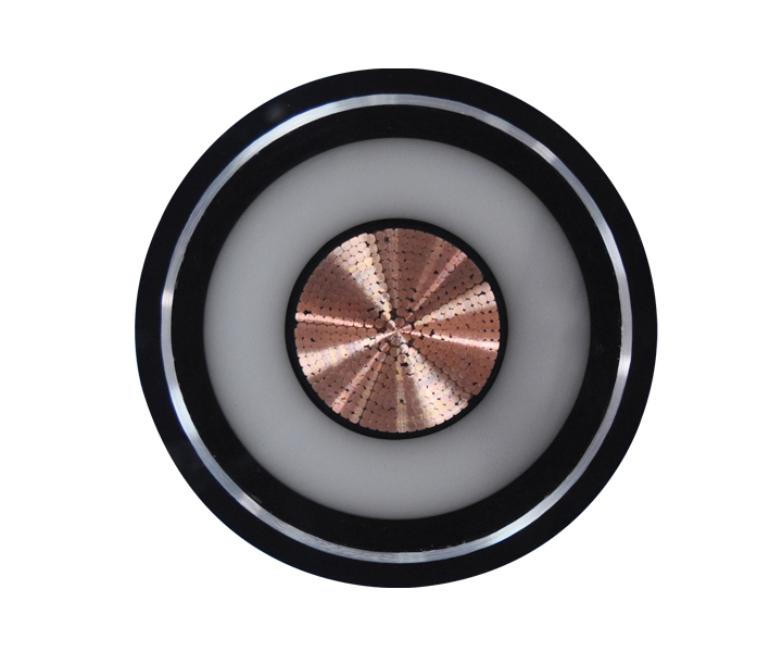
The choice of conductor material establishes the fundamental electrical properties of the circuit. Copper and aluminum dominate the industry, each offering distinct advantages and trade-offs. Copper serves as the standard benchmark due to its superior electrical conductivity. It offers less resistance per unit of cross-sectional area, generating less heat for a given current. This allows for smaller overall diameters, making copper ideal for space-constrained installations or complex routing through existing infrastructure.
Aluminum provides a lighter alternative. However, its lower conductivity means an aluminum conductor requires a larger cross-sectional area to achieve the equivalent capacity of copper. This increased size impacts conduit fill calculations and requires larger bending radii. Material choice also heavily impacts termination requirements. Aluminum exhibits cold flow under pressure and oxidizes rapidly when exposed to air. The resulting aluminum oxide acts as an insulator, increasing resistance and heat at connection points. Installers must use specific anti-oxidant compounds and dual-rated lugs to mitigate galvanic corrosion risks and ensure long-term joint stability.
Conductor Material Comparison
Property | Copper | Aluminum |
|---|---|---|
Electrical Conductivity | Standard Benchmark (100% IACS) | Lower (~61% IACS) |
Cross-Sectional Area for Equal Ampacity | Baseline | Requires ~1.5x larger area |
Weight | Heavier | Lighter (easier to pull over long distances) |
Termination Requirements | Standard lugs, highly stable | Requires oxide inhibitors and specialized compression lugs |
An inverse relationship exists between cross-sectional area and electrical resistance. Larger conductors provide a wider path for electron flow, directly reducing resistance. Lower resistance means less heat generated per ampere of current. Consequently, increasing the physical size of the conductor directly increases its capacity. Engineers select specific wire gauges or millimeter-squared designations to match the anticipated load.
In alternating current (AC) systems, the skin effect complicates this relationship. Alternating magnetic fields push the current toward the outer surface of the conductor. The center of a large solid conductor carries very little current, effectively wasting material and increasing the AC resistance compared to its DC resistance. This phenomenon limits the effective use of the entire cross-section. Higher frequencies exacerbate the skin effect. To combat this, engineers specify stranded conductors or specialized segmental designs for a High Current Power Cable. Segmental conductors divide the core into insulated sections, forcing current to distribute more evenly across the total area, thereby maximizing effective capacity in heavy AC applications.
The dielectric material surrounding the conductor dictates the absolute maximum operating temperature. Different chemical compositions withstand varying levels of thermal stress before degrading. Polyvinyl Chloride (PVC) typically carries a maximum rating of 70°C or 90°C. Its lower thermal ceiling restricts the amount of current the underlying conductor can carry. Exceeding this limit causes PVC to soften, deform, and eventually fail.
Cross-linked Polyethylene (XLPE) and Ethylene Propylene Rubber (EPR) offer superior thermal stability. These thermoset materials routinely carry ratings of 90°C or 105°C for continuous operation, and can withstand significantly higher temperatures during short-circuit events. Upgrading to a higher-temperature insulation can increase overall capacity without increasing the physical conductor size. This presents a powerful specification strategy. If conduit space is limited, switching from PVC to XLPE allows the existing wire gauge to safely carry more current, potentially avoiding infrastructure modifications.
Common Insulation Materials and Thermal Ratings
Insulation Material | Standard Continuous Temperature Rating | Short-Circuit Temperature Limit | Typical Application Environment |
|---|---|---|---|
Polyvinyl Chloride (PVC) | 70°C to 90°C | 160°C | Low voltage, indoor, general commercial |
Cross-linked Polyethylene (XLPE) | 90°C | 250°C | Medium to high voltage, industrial, underground |
Ethylene Propylene Rubber (EPR) | 90°C to 105°C | 250°C | High flexibility requirements, harsh industrial |
Medium and high voltage circuits utilize metallic shields and armor for stress control and physical protection. However, these metallic components introduce additional thermal constraints. Alternating current flowing through the main conductor induces voltage in the parallel metallic sheath. If the sheath is grounded at multiple points, circulating currents flow through the shield. These circulating currents, along with eddy currents, generate additional heat.
This secondary heat source raises the overall temperature of the assembly, forcing a reduction in the primary conductor's allowable current. To mitigate these losses and maximize capacity, engineers employ specific grounding methods. Single-point grounding eliminates the closed loop, preventing circulating currents entirely, though it introduces standing voltages at the ungrounded end. For longer runs, cross-bonded grounding transposes the shields across different phases, cancelling out the induced voltages and minimizing heat generation while maintaining safe grounding practices.
The surrounding environment plays a massive role in determining effective capacity. The fundamental driver of heat dissipation is the temperature differential between the hot conductor and the cooler surrounding ambient environment. A larger differential allows heat to escape rapidly. A smaller differential restricts heat flow. Therefore, the ambient temperature directly determines the allowable heat rise before the insulation reaches its maximum rating.
If an XLPE insulated circuit operates in a standard 30°C environment, it has a 60°C allowable heat rise before hitting its 90°C limit. If routed through a high-heat environment like a boiler room operating at 50°C, the allowable heat rise shrinks to 40°C. The current must be drastically reduced to prevent exceeding the limit. Routing circuits through extreme environments introduces severe implementation risks. Strict NEC and IEC requirements mandate ambient temperature correction factors when installations face direct solar radiation. Sunlight adds external radiant heat, requiring additional derating to ensure the internal temperature remains safe during peak daylight hours.
Underground installations face unique thermal challenges. Air allows for convective cooling, but buried infrastructure relies entirely on conduction through the surrounding earth. The ability of the soil to conduct heat away from the installation is measured as thermal resistivity. Soil composition, density, and moisture content heavily dictate this value. Damp, densely packed clay dissipates heat efficiently. Dry, loose sand acts as a thermal blanket, trapping heat and severely limiting capacity.
Moisture migration presents a significant risk. As a buried circuit generates heat, it dries out the surrounding soil. Dry soil has a higher thermal resistivity, which traps more heat, further drying the soil. This vicious cycle leads to thermal runaway and catastrophic failure. To mitigate this risk, engineers utilize engineered thermal backfill. Materials like Fluidized Thermal Backfill are poured into the trench around the conduits. These engineered mixtures maintain a consistent, low thermal resistivity regardless of surrounding moisture conditions, ensuring reliable heat dissipation and protecting the underground circuit.
Proper underground installation requires strict adherence to field procedures:
Conduct soil thermal resistivity testing along the proposed trench route.
Calculate the worst-case scenario assuming maximum summer soil temperatures and minimum moisture content.
Excavate the trench to the required depth, ensuring proper spacing between parallel duct banks.
Install the conduits and secure them with spacers to prevent shifting during backfill.
Pour engineered thermal backfill to completely encase the conduits, eliminating air voids that trap heat.
How circuits are physically arranged dictates their ability to shed heat. Bundling multiple active circuits together creates a severe thermal bottleneck. This proximity effect introduces mutual heating. The inner conductors in a tight bundle cannot dissipate heat into the ambient air; they only radiate heat into adjacent, already-hot conductors. This restricts airflow and causes localized temperature spikes.
Electrical codes mandate severe derating penalties for grouped conductors. If you run three active conductors in a conduit, you might use 100% of the baseline capacity. If you run nine active conductors in that same conduit, codes typically force a derating to 70% of the baseline capacity. Engineers must calculate spacing requirements meticulously on cable trays to minimize these grouping penalties. Maintaining a minimum distance of one cable diameter between adjacent circuits allows natural convective airflow to cool the installation, often avoiding the need for grouping derating factors entirely.
The physical enclosure surrounding the installation alters heat dissipation capabilities. Installations in free air offer the highest capacity. Natural convection currents constantly move cooler air across the surface, carrying heat away efficiently. Open ladder trays maximize this convective cooling.
Conversely, installing circuits in conduits, ducts, or concrete-encased duct banks restricts capacity. The heat must transfer through the air gap inside the conduit, through the conduit wall, and into the surrounding environment. Each layer adds thermal resistance. Furthermore, the conduit material itself introduces variables. Routing AC circuits through magnetic conduits like rigid galvanized steel can introduce induction heating. The alternating magnetic field induces eddy currents in the steel conduit, generating external heat that further reduces the allowable current of the conductors inside. Non-magnetic conduits, such as PVC or aluminum, eliminate this induction heating penalty.
Accurate specification requires a deep understanding of the anticipated load profile. Continuous loads operate for three hours or more and require strict adherence to base ampacity calculations. Intermittent or peak loads behave differently. The thermal inertia of large conductors means they do not heat up instantly. They can often sustain temporary overcurrents during motor startups or short peak cycles without exceeding insulation limits. However, relying on thermal inertia requires precise engineering analysis.
Modern electrical environments are saturated with non-linear loads, such as variable frequency drives, LED lighting, and server power supplies. These solid-state devices draw current in short pulses, introducing harmonic currents into the system. Triplen harmonics are particularly problematic in three-phase systems. Unlike fundamental currents that cancel out in the neutral, triplen harmonics add together in the neutral conductor. This causes excessive heating in the neutral, often exceeding the phase conductors' temperatures. Managing this requires strict derating of the phase conductors or the specification of oversized, fully rated neutral conductors to handle the harmonic load safely.
Future-proofing represents another evaluation dimension. Facility loads rarely decrease over time. Specifying exact-match conductors based on today's load leaves zero room for expansion. A common strategy involves oversizing infrastructure by 15% to 25% during the initial installation. The incremental material requirement of slightly larger copper or aluminum is minimal compared to the massive labor required to pull new, larger circuits through existing conduits when facility expansion inevitably occurs.
Electrical design is a strictly regulated engineering discipline. Authoritative frameworks govern every calculation. In North America, the National Electrical Code (NEC), specifically Article 310, provides the mandatory tables and formulas for calculating safe operational thresholds. Internationally, IEC 60287 serves as the benchmark standard for calculating continuous current ratings.
Engineers must utilize these standardized tables to apply ambient temperature correction factors and grouping adjustments. Failure to document derating compliance carries severe consequences. Inspectors will reject non-compliant installations, delaying project commissioning. Manufacturers will void warranties if products operate outside specified thermal limits. Most importantly, non-compliance exposes the engineering firm and facility owner to immense liability in the event of an electrical fire or equipment failure.
Specifying infrastructure requires evaluating long-term operational impacts against initial material requirements. Selecting an exact-match conductor minimizes upfront material volume. However, smaller conductors have higher electrical resistance. This higher resistance translates directly into continuous energy losses over the life of the installation. The facility pays for this wasted energy every month as heat dissipates into the environment.
Selecting larger conductors increases the upfront material volume. However, the larger cross-sectional area drastically reduces electrical resistance. This minimizes energy losses. Over a 20- or 30-year operational lifecycle, the energy savings achieved by utilizing larger, more efficient conductors frequently offset the initial material premium. Evaluating this balance between upfront material investment and long-term energy efficiency is a hallmark of sophisticated electrical system design.
Current carrying capacity is never a static number pulled from a basic chart. It is a highly dynamic variable dictated by the complex interplay of conductor materials, insulation thermal limits, environmental conditions, system loads, and installation geometry. Failing to account for ambient heat, grouping penalties, or harmonic loads guarantees premature infrastructure failure and severe safety risks. Accurate specification demands a rigorous, multi-variable engineering approach.
Decision-makers should sequence their evaluation logically. First, define the exact load profile, including continuous requirements and potential harmonic distortions. Second, assess the worst-case environmental conditions, noting maximum ambient temperatures and soil thermal resistivity. Third, determine the installation routing to calculate necessary grouping and conduit derating factors. Finally, select the specific material and insulation combination that meets the fully derated requirement while allowing room for future expansion.
To ensure safety and efficiency on your next project, follow these actionable steps:
Audit your proposed routing paths to identify high-heat areas or severe grouping bottlenecks before finalizing conduit layouts.
Consult with a licensed electrical engineer to perform precise load calculations, specifically accounting for non-linear loads and harmonic currents.
Request detailed specification sheets and thermal derating tables from your manufacturer to verify performance under your specific site conditions.
Evaluate the long-term energy savings of up-sizing conductors to reduce continuous energy losses over the facility's lifecycle.
A: Current carrying capacity, or ampacity, is the maximum continuous current a conductor can carry without exceeding its thermal insulation limits. This metric is highly dependent on environmental conditions, installation methods, and the physical properties of the materials used.
A: Length does not change the fundamental thermal ampacity limit. However, increased length increases electrical resistance, leading to voltage drop. Engineers frequently must upsize long circuits to prevent excessive voltage drop at the load, even if the baseline thermal capacity is sufficient.
A: Higher ambient temperatures reduce the allowable temperature rise of the conductor. With a smaller delta between the ambient air and the insulation's maximum rating, the circuit can dissipate less heat. This decreases the amount of current it can safely carry, requiring mandatory derating.
A: Copper offers superior electrical conductivity compared to aluminum. This allows copper to carry more current within a smaller cross-sectional area. The smaller diameter makes copper easier to pull through conduits, requires less space in tight installations, and generally provides more stable termination points.
A: Derating factors are calculated using standardized regulatory tables, such as NEC Article 310 or IEC standards. These tables provide specific percentage reductions based on the number of current-carrying conductors bundled together in a conduit or tray, which restricts natural heat dissipation.
A: Exceeding capacity causes internal heat generation to outpace dissipation. This leads to accelerated insulation aging, softening, and eventual melting. Ultimately, this thermal runaway results in short circuits, equipment damage, and severe risks of electrical fires.
A: No, thicker insulation does not increase capacity; it often adds thermal resistance. Instead, the chemical thermal rating of the material dictates the maximum allowable operating temperature and, consequently, the capacity ceiling.
 简体中文
简体中文 

