

Views: 0 Author: Site Editor Publish Time: 2026-08-17 Origin: Site


Underspecified electrical infrastructure hides severe safety hazards and massive operational costs. Cables operate out of sight, making them easy to ignore until a catastrophic failure occurs. Relying on inadequate cables in demanding environments guarantees failure. It leads directly to thermal degradation, electrical shorts, compliance failures, and catastrophic equipment downtime. Facility managers face immense potential liability when infrastructure fails under load. Upgrading infrastructure proactively prevents these invisible threats from halting production lines. Selecting the exact Power Cable requires a rigorous, systematic evaluation framework. You must match load requirements, environmental stressors, and safety standards to your specific application. Guesswork in electrical procurement is dangerous. Precision ensures safety, efficiency, and uninterrupted production.
Ampacity and voltage drop calculations must dictate American Wire Gauge (AWG) selection; baseline assumptions lead to overheating, power loss, and equipment failure.
Environmental variables—including chemical exposure, temperature extremes, and mechanical abrasion—determine the necessary insulation and jacketing materials.
Regulatory compliance (UL, NEC, OSHA) is non-negotiable for industrial power cables to mitigate liability and ensure operational safety.
Total cost of ownership requires balancing upfront material and procurement costs against long-term reliability, energy efficiency, and reduced maintenance cycles.
Calculating continuous versus peak current establishes your baseline capacity requirements. This measurement is known as ampacity. Ampacity dictates how much current a conductor can carry without exceeding its temperature rating. Accurate ampacity calculations maximize energy efficiency across the facility. You must account for startup surges in heavy machinery. Induction motors draw significantly more current upon startup than during continuous operation. This inrush current can spike to six times the full-load amps for several seconds. The National Electrical Code requires sizing conductors at 125% of the continuous load for devices operating three hours or more. Failing to size for peak continuous current melts insulation and causes immediate shorts. You must evaluate the entire circuit path, including ambient temperature derating factors, to establish the true ampacity required for your specific installation.
Extended cable runs suffer from inevitable voltage drop. Electrical resistance increases with cable length. You must compensate for this drop in large industrial facilities. Industry standards recommend keeping voltage drop below 3% for branch circuits and 5% for overall feeders. A 300-foot run powering a heavy motor experiences significant voltage drop if undersized. This forces the motor to draw more current to maintain wattage. It generates excess heat and destroys the motor insulation over time. You calculate voltage drop using the conductor's resistance per 1000 feet, the total load current, and the exact distance of the run. Upsizing the wire gauge is the most effective method to mitigate this issue.
Consequences of unmitigated voltage drop include:
Overheating of industrial motor windings and premature bearing failure.
Erratic behavior in sensitive electronic components and PLCs.
Inconsistent power delivery to automated robotics and welding equipment.
Increased energy consumption due to thermal losses in the conductor.
Nuisance tripping of circuit breakers and blown fuses.
Match equipment inlet types, voltage ratings, and phase requirements carefully. Single-phase power suits lighter industrial tools, temporary lighting, and fractional horsepower motors. Three-phase power drives heavy industrial motors, large-scale HVAC systems, and heavy manufacturing equipment. Three-phase systems demand specific multi-conductor cable configurations to balance the electrical load across all legs. You must verify whether the equipment requires a neutral wire, which dictates whether you need a three-conductor or four-conductor assembly.
Connector security is equally vital for operational stability. Standard straight-blade plugs work adequately for static, low-risk setups where equipment remains stationary. High-vibration environments require locking connectors. The NEMA L-series provides excellent mechanical locking mechanisms. These connectors twist and lock into the receptacle. They prevent accidental disconnections during heavy machinery operation. This simple upgrade eliminates sudden power loss and prevents dangerous electrical arcing. Factory floors with heavy foot traffic or moving material handling equipment benefit immensely from locking connections.
Ambient temperature extremes heavily impact overall cable performance. You must contrast environmental heat with the internal heat generated by the conductor under load. High ambient temperatures reduce the effective ampacity of the installation. When ambient temperatures exceed standard baselines, you must apply correction factors to derate the capacity safely. Routing wires through boiler rooms, foundries, or unventilated ceiling spaces demands high-temperature insulation. Conversely, cold environments make standard insulation brittle. PVC jackets will crack and shatter if flexed in sub-zero freezer facilities or outdoor winter installations.
Mechanical wear scenarios dictate physical durability requirements. Evaluate your installation for specific mechanical stressors. Dynamic installations require vastly different mechanical defenses than static routing. A cable sitting in a rigid conduit faces zero mechanical stress after installation. A cable attached to a CNC machine gantry flexes thousands of times per day.
Assess your facility for these mechanical hazards:
Continuous flexing in automated tracks, drag chains, and robotic arms.
Surface abrasion from dragging across rough concrete floors or steel grating.
Crush risks from forklift traffic, pallet jacks, or heavy equipment movement.
Tension and pulling forces in suspended overhead installations or vertical drops.
Impact forces from dropped tools or falling debris in heavy manufacturing zones.
Industrial facilities expose infrastructure to harsh chemical elements. Assess the risks of cutting oils, hydraulic fluids, and industrial solvents. Standard jackets swell, soften, and eventually dissolve when exposed to aggressive petrochemicals. UV exposure degrades standard jackets rapidly in outdoor installations, causing the outer sheath to crack and expose the inner conductors. Moisture ingress causes internal corrosion and catastrophic electrical shorts. Submerged applications or washdown zones in food processing plants require specialized water-resistant constructions. These environmental factors dictate the exact physical defense requirements for your Industrial Power Cable.
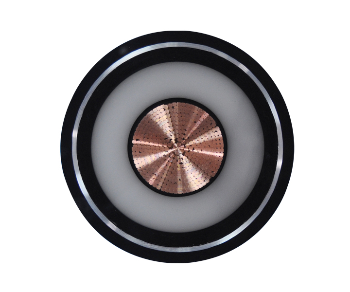
Copper and aluminum dominate as primary conductor materials. Copper offers superior electrical conductivity and physical flexibility. It fits easily into tight enclosures and withstands heavy vibration without fracturing. Copper remains the standard for nearly all flexible cords and equipment wiring. Aluminum reduces overall weight and upfront material expenses. It is highly effective for long, static feeder runs and large service entrances. However, aluminum carries long-term oxidation risks. Aluminum expands and contracts at a different rate than copper when heated. This thermal cycling loosens connections over time, known as cold flow. You must use dual-rated lugs and apply dielectric anti-oxidant paste to prevent high-resistance connections when terminating aluminum.
Sizing the American Wire Gauge (AWG) correctly prevents overheating. A lower AWG number indicates a thicker wire capable of carrying more current. Standard heavy-duty use typically requires 12 or 14 AWG conductors for basic 15-amp to 20-amp circuits. High-draw industrial equipment demands thicker gauges. You must scale up to 10 AWG, 8 AWG, or lower for massive power requirements. A 50-amp welding receptacle requires at least 6 AWG copper. Undersizing the gauge creates a bottleneck. The resistance generates heat, which degrades the insulation and eventually causes a fire.
Conductor construction dictates physical flexibility. Solid conductors consist of a single thick wire. They suit rigid, permanent installations where movement never occurs, such as inside commercial conduit. Stranded conductors consist of multiple smaller wires bundled together. They provide necessary flexibility for installation and operation. Continuous flex ratings are mandatory for moving machinery. Robotic arms and automated tracks require highly stranded conductors, often utilizing hundreds of hair-thin copper strands, to survive millions of flex cycles without fracturing.
Insulation protects the bare conductor and prevents electrical leakage. Dielectric strength measures the material's ability to act as an insulator without breaking down under high voltage. Thermoplastic materials like PVC offer basic, cost-effective protection. However, PVC melts under extreme heat and becomes rigid in the cold. Thermoset materials provide superior thermal stability. Cross-Linked Polyethylene (XLPE) and Ethylene Propylene Rubber (EPR) dominate high-performance applications. The cross-linking process changes the molecular structure to prevent melting. They boast higher dielectric strength and elevated melting points. They will not deform during temporary electrical overloads or short circuits.
Jacketing defends the internal components from external abuse. Polyurethane (PUR) resists severe mechanical abrasion and tearing. Neoprene handles oil, weather, and ozone exposure exceptionally well. Chlorinated Polyethylene (CPE) offers excellent broad-spectrum chemical resistance. Map these specific chemical and mechanical resistance profiles to your facility hazards.
Common Industrial Jacketing Materials and Applications
Material Type | Primary Resistance | Best Industrial Application |
|---|---|---|
Polyurethane (PUR) | Abrasion, Tearing, Cutting | Robotics, Drag Chains, Factory Floors |
Neoprene | Oil, Weather, Ozone | Outdoor Equipment, Refineries |
Chlorinated Polyethylene (CPE) | Chemicals, Heat, Flame | Chemical Plants, Harsh Environments |
Polyvinyl Chloride (PVC) | Moisture, General Wear | Static Indoor Routing, Light Industry |
Thermoplastic Elastomer (TPE) | Flexing, Extreme Cold | Cold Storage, Automated Machinery |
High-density industrial settings generate massive Electromagnetic Interference (EMI). Variable frequency drives, large motors, and welding equipment emit strong electromagnetic fields. Sensitive control signals degrade rapidly under EMI exposure. Shielding mitigates this interference effectively by intercepting the noise and directing it to ground.
Foil shielding provides comprehensive coverage against high-frequency interference. It is thin, lightweight, and best suited for static installations where the foil will not tear. Braided copper shielding offers superior physical durability. It protects against low-frequency interference and maintains integrity during flexing. Many high-performance designs utilize a combination of foil and braid for maximum protection. Improper shield grounding creates ground loops, introducing noise instead of eliminating it. Best practice involves grounding the shield at the source end only, leaving the equipment end floating to prevent circulating currents.
Proper grounding conductor sizing is equally critical. Grounding ensures fault path integrity during electrical surges. If a short circuit occurs, the ground wire directs the current safely away from the equipment chassis and back to the panel to trip the breaker. Correct grounding protects personnel from fatal shocks. It prevents catastrophic equipment damage and facility fires. The ground wire must be sized proportionally to the phase conductors to handle the maximum potential fault current without melting.
Regulatory compliance ensures baseline safety and performance. UL (Underwriters Laboratories) listings prove the product passed rigorous safety testing. CSA certifications validate adherence to North American industry standards. You cannot bypass these certifications in industrial environments. Uncertified products introduce unacceptable risks into your facility and void insurance policies. Inspectors will immediately flag unlisted equipment during routine facility audits.
The National Electrical Code (NEC) dictates specific installation rules. NEC Article 400 governs flexible cords and cables, outlining exactly where you can and cannot use them. For example, you cannot run flexible cords through walls, ceilings, or floors. Hazardous and classified locations require specialized constructions. Environments with explosive gases, combustible dust, or ignitable fibers demand strict adherence to NEC Chapter 5. You must use explosion-proof fittings and specifically rated wiring methods in these zones. Failing to meet NEC compliance invites severe legal liability. It results in failed inspections and immediate operational shutdowns.
Global equipment compatibility requires strict standard adherence. North American facilities rely on NEMA standards for plugs and receptacles. NEMA configurations dictate voltage, amperage, and grounding setups. A NEMA L5-20 plug will only fit a matching L5-20 receptacle, preventing operators from plugging 120V equipment into a 240V source. International operations utilize IEC standards for cord sets. IEC 60320 defines common international power connectors used on servers, test equipment, and machinery.
Mismatching these standards causes immediate integration failures. Material safety also heavily impacts procurement decisions. RoHS compliance ensures products lack hazardous heavy metals like lead, mercury, and cadmium. REACH compliance regulates the environmental impact of chemical substances used in manufacturing. Procuring compliant materials protects your workforce from toxic exposure and aligns with corporate sustainability goals.
Dense routing traps significant thermal energy. Bundled wires cannot dissipate heat effectively into the ambient air. You must apply ampacity derating when bundling multiple circuits together. The NEC mandates specific derating percentages based on bundle size and conduit fill. If you run more than three current-carrying conductors in a single conduit, you must reduce their allowable ampacity. Ignoring derating formulas leads to melted insulation and electrical fires inside the conduit.
Excessive length presents another severe hazard. Coiled slack acts as an inductor. It generates dangerous localized heat and reduces overall power efficiency. Never leave excess slack coiled on the facility floor or zip-tied tightly in a rack. The magnetic fields overlap, multiplying the heat generation until the jacket melts.
Integrate wiring precisely with Power Distribution Units (PDUs). Use exact lengths in space-constrained industrial racks. Precise routing maximizes airflow and cooling efficiency. It prevents accidental disconnections caused by tangled wires. Label both ends of every run to simplify troubleshooting and maintenance.
Every product features a minimum bend radius specification. This metric defines how tightly you can bend it without causing damage. Violating this radius during installation fractures internal copper strands. It places immense stress on the insulation layer, causing micro-tears. These tears eventually lead to electrical shorts. A common rule of thumb requires a bend radius of at least eight times the outer diameter for unshielded designs, and twelve times for shielded designs.
Pulling through conduit requires calculating maximum pulling tension. Exceeding this tension stretches the copper, reducing its cross-sectional area and increasing resistance. It also damages the outer jacket against the conduit walls. Use appropriate pulling lubricants to reduce friction and utilize mechanical tuggers with tension meters for heavy pulls.
End finishing and terminations demand meticulous execution. Poor terminations create high-resistance connections. These connections cause localized heating and act as primary fire hazards. Follow these exact steps for safe terminations:
Measure and mark the exact strip length required by the specific lug or terminal block.
Use calibrated stripping tools to remove the jacket and insulation without nicking the underlying copper strands.
Apply anti-oxidant compound immediately if terminating aluminum conductors.
Insert the bare strands fully into the terminal, ensuring no stray strands remain outside the connector.
Utilize proper hydraulic crimping tools with the correct die size for compression lugs.
Apply the exact torque specifications listed by the manufacturer to all mechanical terminal screws using a calibrated torque wrench.
Inspect all completed connections with thermal imaging cameras under full load to verify no hot spots exist.
Procurement decisions balance immediate expenses against long-term performance. Over-specifying wastes valuable capital on unnecessary capacity. Buying 8 AWG wire for a 15-amp load provides no additional benefit and makes installation significantly harder due to the increased stiffness and diameter. However, under-specifying creates severe operational hazards. It leads directly to electrical fires, compliance fines, and massive downtime. Saving a few dollars on thinner wire or cheaper jackets costs thousands in lost production when the line halts.
Custom cord set put-ups offer significant advantages over off-the-shelf lengths. Exact lengths minimize slack and reduce tripping hazards on the factory floor. They optimize power delivery by eliminating unnecessary resistance. Custom configurations allow you to specify the exact connector, jacket, and shielding required for your specific machine. Standardizing on a few highly versatile, custom types across the facility simplifies maintenance and reduces spare parts inventory. This precision maximizes operational longevity and reduces emergency maintenance cycles.
Audit your facility to document exact load profiles, ambient temperature extremes, and chemical exposure risks for every machine.
Calculate precise ampacity requirements and voltage drop limits to determine the exact AWG needed for your longest runs.
Specify thermoset insulation and heavy-duty jacketing materials that directly combat your identified environmental hazards.
Verify all selected materials carry the appropriate UL listings and meet NEC requirements for your specific facility classification.
Consult with a licensed electrical engineer to finalize connector types and request certified samples before executing a facility-wide upgrade.
A: Standard cords handle light loads in climate-controlled environments. Industrial variants feature thicker AWG conductors, ruggedized jacketing, and specialized insulation. They withstand chemical exposure, extreme temperatures, and heavy mechanical abrasion while delivering higher continuous ampacity for heavy machinery.
A: Calculate the continuous and peak current requirements of your machinery. Factor in the total length of the run to account for voltage drop. Use NEC ampacity tables to select an AWG that safely exceeds your maximum load, applying the 125% rule for continuous operation.
A: Thermoset materials like Cross-Linked Polyethylene (XLPE) or Ethylene Propylene Rubber (EPR) are ideal. They offer superior thermal stability and higher melting points compared to standard thermoplastic options like PVC, preventing deformation during overloads.
A: UL certification proves the product has passed rigorous, independent safety testing. It ensures the materials handle their rated voltage and temperature without failing. Using non-certified materials violates safety codes, fails inspections, and voids facility insurance policies.
A: Extended lengths increase electrical resistance, causing voltage drop that strains motors and increases heat. Coiled slack acts as an inductor, trapping thermal energy. This localized heating degrades insulation rapidly and creates a significant fire hazard.
A: Use locking connectors in high-vibration environments or areas with heavy foot traffic. They physically twist and lock into the receptacle, preventing accidental disconnections that cause sudden equipment shutdowns, operational delays, or dangerous arc flashes.
 简体中文
简体中文 

