

Views: 0 Author: Site Editor Publish Time: 2026-09-16 Origin: Site


Electrical failures in maritime environments carry severe safety and operational consequences. Continuous vibration, saltwater ingress, and extreme temperatures rapidly degrade standard industrial components. Project engineers and procurement teams face strict baseline requirements when specifying wiring for valves, pumps, navigation equipment, and instrumentation. Premature cable failure leads to immediate system downtime and complex replacement logistics at sea. Specifying purpose-built, certified Marine Control Cable serves as a baseline requirement for operational continuity, safety, and strict regulatory compliance in offshore and vessel projects. Environmental stressors dictate cable engineering from the conductor up to the outer jacket. We will explore which classification society approvals matter most and how to match cable specifications to your specific maritime application to ensure long-term system integrity.
Regulatory Compliance is Mandatory: Utilizing cables without proper classification society approvals (e.g., ABS, DNV, Lloyd's) introduces severe liability and insurance risks for offshore projects.
Vibration and Fatigue Resistance: Fine copper stranding and specialized jacketing are engineered specifically to absorb continuous mechanical stress, preventing the metal fatigue common in standard industrial cables.
Environmental Survivability: Halogen-free, flame-retardant (LSZH), and moisture-resistant materials protect against saltwater corrosion, oil exposure, and toxic smoke generation in enclosed shipboard spaces.
Maritime environments present a harsh combination of destructive forces. Standard industrial cables fail quickly under these conditions. Continuous mechanical vibration acts as a primary threat to electrical continuity. Ship engines, heavy thrusters, and offshore drilling equipment generate relentless kinetic energy. This vibration travels through the vessel structure directly into the cable trays. Rigid conductors cannot absorb this movement. They experience rapid work hardening, leading to microscopic fractures and eventual metal fatigue. Once the conductor breaks, control signals drop instantly.
Chemical degradation poses an equally severe threat to wiring infrastructure. Saltwater spray is highly corrosive, attacking exposed metals and degrading inferior plastics. Oil spills, hydraulic fluid leaks, and drilling muds introduce aggressive hydrocarbons into the cable routing areas. These chemicals break down standard cable jackets. The jacket swells, softens, and eventually splits open. Ultraviolet (UV) radiation on open decks accelerates this breakdown, causing plastics to become brittle and crack. These cracks allow moisture to penetrate the cable core, causing short circuits and total system failure.
Thermal extremes further complicate maritime cable selection. Open decks experience blistering heat during the day, while enclosed engine rooms generate massive ambient temperatures. Cables must operate flawlessly in these high-heat zones without melting or losing dielectric strength. Conversely, arctic offshore platforms face sub-zero conditions. Standard PVC jackets freeze and shatter upon impact in freezing weather. Specialized marine jackets must maintain flexibility across this wide temperature gradient.
Control signal loss on critical infrastructure triggers immediate operational crises. Emergency shutdown systems rely on uninterrupted data transmission. If a control cable fails, the shutdown sequence may not activate during an emergency. Motor control centers require precise signaling to operate heavy machinery. Ballast pumps depend on accurate sensor data to maintain vessel stability. A single severed connection can compromise the entire vessel.
Diagnosing and replacing failed infrastructure at sea presents a logistical nightmare. Offshore platforms operate in remote, hostile locations. Identifying a specific cable fault within miles of bundled wiring takes days of manual testing. Pulling new cables through sealed bulkheads requires specialized labor and permits. The operational downtime during this repair process halts production entirely. The logistical realities make premature cable failure an unacceptable risk for any marine operation.
The typical failure sequence for undersized or improper cables follows a predictable pattern:
Micro-fractures develop in the rigid copper conductor due to continuous engine vibration.
Electrical resistance increases across the fractured connection, generating localized heat.
The control signal degrades, causing intermittent sensor faults at the monitoring station.
Complete conductor separation occurs, triggering an immediate system fault and equipment shutdown.
Maintenance crews must trace the fault through hundreds of meters of bundled tray wiring to locate the break.
Conductor engineering dictates the mechanical lifespan of the cable. Standard solid cores or coarse stranding cannot survive maritime vibration. Fine copper stranding is an absolute necessity for shipboard wiring. Class 2 or Class 5 stranded conductors absorb multidirectional movement. The fine individual strands flex independently, preventing the metal fatigue that destroys rigid wires. The cable bends and moves with the ship's natural resonance without suffering structural damage.
Engineers must balance this flexibility with high tensile strength. Offshore rigs and deep vessel shafts require long vertical cable suspensions. The cable must support its own weight over these massive drops. If the tensile strength is too low, the conductor elongates. Elongation thins the copper, increasing electrical resistance and straining the insulation, which leads to micro-tears. Proper marine cables integrate strength members or utilize optimized lay lengths to prevent stretching during vertical installations.
The choice between tinned copper and bare copper requires careful consideration. Bare copper oxidizes rapidly in high-humidity environments. Salt-laden air accelerates this corrosion process. Tinned copper conductors feature a thin layer of tin over each individual strand. This tin coating provides a sacrificial barrier against oxidation. It also prevents galvanic corrosion when terminating the cable to dissimilar metals. Tinned copper ensures reliable conductivity throughout the vessel's lifespan.
Material science defines the safety profile of marine wiring. Enclosed vessel spaces trap smoke and toxic gases during a fire. Standard PVC insulation releases lethal halogen gas when burned. Low Smoke Zero Halogen (LSZH) materials are a strict safety requirement. LSZH jackets emit minimal smoke and do not release toxic halogens. This visibility and breathable air give personnel time to evacuate. It also protects sensitive electronic equipment from corrosive soot damage.
Understanding the difference between flame-retardant and fire-resistant cables is vital for system design. Flame-retardant cables, rated SHF1 or SHF2, prevent fire from traveling along the cable tray. They self-extinguish when the primary heat source is removed. However, they will eventually melt in a sustained blaze. Fire-resistant cables comply with stringent IEC 60331 standards. They incorporate mica glass tape around the conductors. This tape forms an insulating ceramic ash when exposed to direct flames. Fire-resistant cables maintain circuit integrity for hours during an active fire. They are mandatory for emergency pumps, fire alarms, and suppression systems.
Insulation materials determine electrical performance and thermal stability. Cross-linked Polyethylene (XLPE) offers exceptional dielectric strength. It withstands high operating temperatures without deforming. Ethylene Propylene Rubber (EPR) provides superior flexibility, especially in cold environments. Both materials resist moisture ingress, maintaining their insulating properties even when submerged or exposed to heavy condensation.
Modern vessels operate as floating industrial plants. Heavy machinery, variable frequency drives (VFDs), and massive generators share tight spaces. This equipment generates intense Electromagnetic Interference (EMI). EMI corrupts low-voltage control signals. Data transmission errors cause valves to misalign and sensors to report false readings. Robust shielding is required for signal integrity.
Shielding strategies vary based on the application. Foil shields provide 100% coverage against high-frequency interference. They are lightweight and thin, but foil can tear under continuous flexing. Braided copper shields offer superior mechanical durability. They protect against low-frequency EMI generated by heavy motors. For critical Offshore Marine Cable applications, engineers often specify combination shields. A foil layer wrapped in a tinned copper braid provides comprehensive EMI protection and mechanical strength.
Shielding Type | Primary Protection | Mechanical Durability | Best Application |
|---|---|---|---|
Aluminum Foil | High-Frequency EMI | Low (Prone to tearing if flexed) | Static data lines, instrumentation |
Tinned Copper Braid | Low-Frequency EMI | High (Excellent flex life) | Motor controls, VFD environments |
Combination (Foil + Braid) | Broadband EMI | High | Critical offshore control systems |
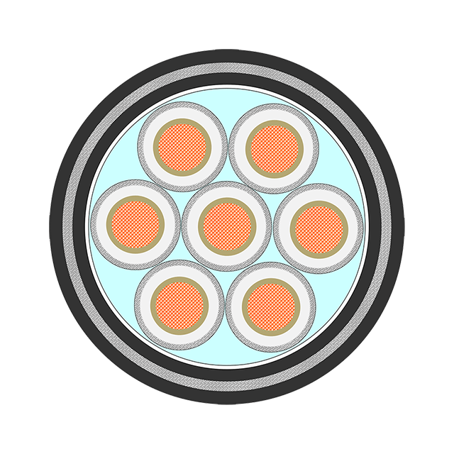
Maritime construction operates under strict international regulations. You cannot install unverified materials on a commercial vessel or offshore rig. Classification societies dictate the testing and approval standards. Major bodies include DNV-GL, the American Bureau of Shipping (ABS), Bureau Veritas (BV), and Lloyd's Register. These organizations subject cables to brutal testing protocols. They verify flame retardancy, chemical resistance, and mechanical durability before issuing type approvals.
Procurement teams must distinguish between marketing terminology and actual certification. "Marine-style" is a marketing term that offers no regulatory guarantee. Certified cables bear the stamp of the classification society. Using uncertified wiring invalidates vessel insurance and guarantees failure during safety inspections. Always demand the official type approval certificates before specifying any cable for a marine project.
No single cable fits every maritime application. You must match the specifications to the exact use case. Fixed shipboard wiring requires different characteristics than flexible routing. Lighting circuits demand different insulation than heavy power circuits. Engineers must map the cable properties to the physical environment.
Offshore platforms face different hazards than commercial vessels. Drilling rigs expose cables to aggressive drilling muds. The NEK 606 standard defines strict mud resistance requirements. Cables on these platforms require specialized SHF2 or mud-resistant jackets. Ice-class vessels operating in arctic waters require extreme cold-weather ratings. These cables must pass cold bend and cold impact tests at -40°C without the jacket cracking.
Application Environment | Primary Hazard | Required Cable Characteristic | Relevant Standard / Rating |
|---|---|---|---|
Enclosed Engine Rooms | High Heat, Toxic Smoke Risk | LSZH, High Thermal Stability | IEC 60332-3, SHF1 |
Offshore Drilling Rigs | Hydrocarbons, Drilling Mud | Mud Resistance, Oil Resistance | NEK 606, SHF2 |
Emergency Fire Systems | Direct Flame Exposure | Circuit Integrity during Fire | IEC 60331 (Fire Resistant) |
Arctic Open Decks | Sub-Zero Temperatures, Ice Impact | Extreme Cold Flexibility | Cold Bend / Impact Tested |
Electrical loads on modern vessels constantly increase. Upgrading systems later is highly disruptive. Engineers must size control cables for current loads while building in transmission capacity. Voltage drop is a serious concern over long shipboard runs. Undersized cables lose voltage over distance, causing sensitive control relays to fail. Proper conductor sizing ensures stable voltage delivery to remote equipment.
Future system expansions require careful planning. Offshore platforms frequently upgrade instrumentation and sensor networks. Pulling new cables through sealed transit blocks is labor-intensive. Smart engineering dictates installing cables with spare core counts. Laying a 12-core cable when only 8 cores are currently needed provides immediate scalability. This foresight accommodates future upgrades without requiring new cable pulls.
Shipboard design operates under strict weight and space limitations. Every kilogram matters for vessel stability. Every square centimeter of cable tray space is contested by piping, ventilation, and structural supports. Robust insulation and thick jacketing provide excellent physical protection. However, they increase the overall diameter and weight of the cable. Engineers face a constant trade-off between physical protection and spatial efficiency.
Manufacturers solve this through advanced material science. Lightweight, thin-wall marine cables utilize highly cross-linked polymers. These materials provide the same dielectric strength and mechanical protection at a fraction of the thickness. Thin-wall cables allow engineers to pack more circuits into existing cable trays. They reduce the overall topside weight of the vessel. This optimization maintains strict regulatory compliance while freeing up valuable space.
The physical size of the cable directly impacts its minimum bending radius. Thick, heavily armored cables require large sweeping bends to prevent internal damage. This becomes problematic in tight shipboard compartments where cables must navigate sharp 90-degree turns through bulkheads. Forcing a stiff cable into a tight bend kinks the conductor and tears the internal shielding.
Engineers must evaluate the routing path before selecting the cable. If the vessel design features narrow transit corridors, highly flexible cables with smaller bend radii are required. This might mean sacrificing heavy steel wire armor in favor of a lighter bronze braid to achieve the necessary flexibility. Balancing mechanical protection with installation reality ensures the cable survives the pulling process.
Even the best cable fails if installed incorrectly. Installation hazards routinely compromise cable integrity before the vessel ever launches. Violating the minimum bending radius is the most common failure. Bending a cable too sharply kinks the conductor, tears the foil shield, and stresses the insulation. Engineers must strictly enforce the manufacturer's bending radius guidelines during routing.
Pulling cables through tight bulkheads introduces significant friction. Complex routing paths require dragging cables over sharp metal edges. This process easily gouges the outer jacket. A compromised jacket allows saltwater to penetrate the core immediately. Installers must use proper pulling lubricants and utilize cable rollers when navigating sharp transitions. Careful handling preserves the environmental seal of the cable.
Follow these installation best practices to prevent mechanical damage:
Calculate the maximum pulling tension for the specific cable gauge before starting the run.
Utilize marine-grade pulling lubricants to reduce friction through sealed bulkheads and tight conduits.
Monitor the bend radius continuously, especially when navigating 90-degree tray transitions.
Secure the cable at regular intervals using stainless steel ties to prevent sagging and vibration wear.
Marine cables require specialized support structures. Standard zip ties and plastic clips degrade quickly in UV light and salt spray. Offshore cable trays and ladders must utilize marine-grade stainless steel or heavily galvanized materials. The cables must be secured tightly to prevent chafing during heavy seas. Loose cables rub against metal trays, wearing through their jackets over time.
Transit sealing systems are critical for maintaining vessel safety. Cables must pass through watertight and fireproof bulkheads. Systems like Roxtec blocks seal the gaps around the cables. These blocks prevent water from flooding adjacent compartments during a hull breach. They also stop fire and smoke from spreading through the cable penetrations. Proper installation of these transit seals is just as important as the cable itself.
Transition zones require special attention. Cables moving from offshore platforms to onshore infrastructure face unique stresses. Shore power connections endure constant movement and tidal shifts. The cable management systems must protect the wiring across both domains. Furthermore, engineers must mitigate galvanic corrosion. Securing a copper-braided cable directly to an aluminum bulkhead creates a battery effect in saltwater. Proper isolation materials prevent this corrosive reaction.
Utilizing standard industrial cables in maritime environments is a dangerous practice. The relentless vibration, chemical exposure, and thermal extremes demand specialized engineering. Purpose-built marine control cable is essential for safety, compliance, and long-term reliability. Protecting your critical infrastructure requires strict adherence to classification society standards and precise application matching.
Procurement and engineering teams must prioritize rigorous certifications. DNV, ABS, and Lloyd's approvals are mandatory for safe operation. Match the environmental ratings to your specific hazards, whether that means mud resistance for drilling rigs or extreme cold flexibility for arctic vessels. Ensure the tensile strength supports vertical drops and the EMI shielding protects sensitive data.
Audit your current project schematics to identify any non-certified industrial cables specified for maritime zones.
Consult the specific classification society guidelines governing your vessel or offshore platform to verify exact material requirements.
Request detailed technical datasheets from certified cable manufacturers to confirm LSZH, SHF1/SHF2, and mud resistance ratings.
Calculate voltage drop and future expansion needs to properly size conductor gauges and core counts before finalizing procurement.
A: Marine control cables feature fine copper stranding to absorb continuous vessel vibration without metal fatigue. They utilize specialized Low Smoke Zero Halogen (LSZH) jackets that resist saltwater, oil, and UV radiation. Standard industrial cables lack these flexible conductors and environmental protections, leading to rapid failure at sea.
A: Bare copper oxidizes rapidly when exposed to salt-laden, high-humidity maritime air. Tinned copper features a thin layer of tin over each strand, providing a sacrificial barrier against corrosion. This ensures reliable conductivity and prevents galvanic corrosion when terminating connections to dissimilar metals.
A: SHF1 and SHF2 are international standards for marine cable jackets. SHF1 indicates a halogen-free, flame-retardant compound suitable for most enclosed shipboard spaces. SHF2 indicates a more robust, cross-linked elastomer jacket that provides enhanced resistance to oil, mud, and extreme temperatures, often used on drilling rigs.
A: Flame-retardant cables self-extinguish to prevent fire from spreading along the cable tray, but they will melt in a sustained blaze. Fire-resistant cables use mica tape to maintain electrical circuit integrity for hours during an active fire, ensuring emergency pumps and alarms keep working.
A: Heavy machinery and generators create severe EMI. Marine control cables use braided tinned copper shields, aluminum foil shields, or a combination of both. These shields block high-frequency and low-frequency interference, ensuring accurate data transmission for sensitive control valves and navigation equipment.
A: Commercial vessels and offshore platforms must use cables approved by recognized classification societies to maintain insurance and regulatory compliance. The most common mandatory certifications come from DNV-GL, the American Bureau of Shipping (ABS), Lloyd's Register, and Bureau Veritas (BV).
 简体中文
简体中文 

