

Views: 0 Author: Site Editor Publish Time: 2026-10-09 Origin: Site


Did you know cable failures cost power grids millions of dollars annually? Unverified lines create massive safety hazards and crippling financial risks. Whether you are installing a new substation, upgrading a regional grid, or commissioning a heavy industrial power system, verifying the quality of your Power Cable is absolutely non-negotiable.
Quality assurance is not a single event. It spans from the highly controlled manufacturing floor to the muddy, unpredictable trenches of the installation site. In this comprehensive guide, you will learn the exact testing procedures that confirm the reliability, safety, and multi-decade longevity of critical electrical infrastructure.
Quality is verified through a highly structured sequence of Routine Tests, Type Tests, and On-Site Commissioning Tests.
Routine factory evaluations ensure every manufactured meter is free of micro-defects prior to deployment.
Type testing scientifically validates the foundational engineering and material integrity. This confirms the design can endure extreme electrical and thermal stresses over a 40-year lifespan.
Pre-energization and on-site field tests are mandatory final steps. They identify any structural damage that may have occurred during transit, trenching, or installation.
Strict adherence to international regulatory frameworks provides empirical proof that the infrastructure satisfies rigorous performance requirements.
Procurement officers, grid engineers, and infrastructure developers must prioritize rigorous testing protocols because high-voltage environments are exceptionally unforgiving. In standard low-voltage applications, a microscopic manufacturing defect might remain dormant for years. However, when dealing with an Ultra High Voltage Cable operating above 110kV, the intense electrical field amplifies even the smallest imperfections. A tiny void in the insulation or a minor impurity can rapidly develop into an electrical tree. Consequently, this leads to dielectric breakdown, catastrophic short circuits, and localized fires.
Furthermore, looking at current industry trends, the rapid expansion of renewable energy is fundamentally shifting testing paradigms. Offshore wind farms and cross-border interconnectors require massive power transfers. As transmission distances increase and environmental conditions become harsher, grid operators are demanding longer continuous spans. We are seeing a major shift toward 127/220kV and even 500kV systems to minimize transmission losses. This structural shift means that quality assurance protocols are evolving to become even more stringent. The focus is now heavily on dynamic mechanical stress and long-term water ingress resistance. The margin for error is shrinking rapidly.
Mitigating these risks through exhaustive evaluation is not just a safety mandate. It is a core financial strategy. Infrastructure projects involving massive transmission lines require immense capital expenditures. Comprehensive testing guarantees that the deployed assets achieve their engineered lifespan. By identifying anomalies before the line is buried or suspended, operators prevent the astronomical costs associated with unplanned outages, emergency excavations, and premature asset replacement.
Routine tests are non-destructive evaluations performed on every single manufactured length before they are spooled and shipped. These assessments are designed to catch variations in the extrusion or wire-drawing processes. They ensure baseline quality for every single batch that leaves the facility.
The first critical evaluation is the measurement of the conductor direct current resistance. This verifies the metallurgical purity and the exact cross-sectional area of the copper or aluminum core. Because resistance is highly temperature-dependent, measurements are taken in a climate-controlled environment. Engineers then mathematically correct the data to a standard reference temperature of 20 degrees Celsius using established coefficients. If the resistance exceeds specified maximum limits, it indicates that the core is impure, undersized, or suffering from broken strands.
Partial Discharge testing is widely considered the most critical routine check for detecting microscopic voids, contaminants, or shield irregularities within the insulation system. A partial discharge is a localized electrical breakdown that does not completely bridge the space between two conductors. During this procedure, the line is subjected to a specific voltage inside an electromagnetically shielded Faraday cage. Highly sensitive equipment measures any discharge events in picocoulombs. A top-tier product must demonstrate zero or near-zero partial discharge. Even a faint trace of activity points to a void that will inevitably degrade the insulation under continuous stress.
Specifically, the High Voltage AC Withstand Test evaluates the overall macroscopic integrity of the insulation. In the testing bay, the distinct hum of a massive series resonant transformer fills the room as it applies an alternating current voltage significantly higher than the rated operating capacity. This over-voltage is held for a predetermined duration, usually 30 to 60 minutes. This ensures the insulation thickness is adequate and the material can handle routine operational stresses without puncturing.
Routine Test Type | Primary Objective | Measurement Unit | Pass or Fail Indicator |
|---|---|---|---|
Conductor Resistance | Verify material purity and core size | Ohms per kilometer | Must not exceed standard maximum limit |
Partial Discharge | Detect micro-voids in insulation | Picocoulombs | Must remain below standard threshold under 5 pC |
HV AC Withstand | Confirm overall dielectric strength | Kilovolts per Minutes | No electrical breakdown during the test duration |
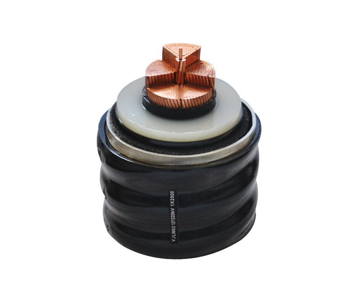
While routine checks verify the manufacturing consistency of every batch, Type Tests are intensive and often destructive evaluations. They are performed only once on a newly designed architecture. The objective is to validate the fundamental engineering, geometry, and material chemistry of XLPE Power Cables before mass production is authorized.
Electrical type testing simulates the absolute extreme conditions the infrastructure might face over its multi-decade lifecycle.
Lightning Impulse Voltage Test: Overhead lines and connected substations are highly susceptible to lightning strikes, which cause massive instantaneous voltage spikes. This procedure subjects the sample to a simulated lightning waveform. It must withstand multiple positive and negative impulses without insulation puncture.
Heating Cycle Voltage Testing: Power grids experience fluctuating loads. The conductor heats up during peak hours and cools down during off-peak times. This thermal cycling causes the cross-linked polyethylene insulation to expand and contract. Here, the sample is subjected to high voltage while simultaneously being heated to a temperature above its maximum operating limit such as 105 degrees Celsius and then cooled. This cycle is repeated numerous times to ensure the insulation does not delaminate from the semiconducting screens.
In addition, the physical properties of the cross-linked polyethylene insulation and the protective outer sheath are equally vital. Non-electrical type tests include tensile strength and elongation at break measurements. These ensure the materials possess the necessary mechanical flexibility to survive installation. Thermal aging tests are also conducted by placing material samples in high-temperature ovens for extended periods. By measuring the degradation of mechanical properties after aging, engineers scientifically extrapolate the material structural stability over a 40-year timeframe.
Even if a product passes all factory tests with perfect scores, the logistical reality of the field changes everything. The brutal processes of shipping across oceans, unspooling a 10-ton reel, and pulling heavy lines through rocky trenches introduce severe risks of physical damage. On-site commissioning tests, performed strictly before connecting to the live grid, are non-negotiable.
Often referred to as a Megger test, this is the first diagnostic performed in the field. A technician uses a megohmmeter to apply a steady DC voltage, measuring the resistance of the insulation in megohms or gigaohms. While it cannot detect microscopic voids, a low reading immediately indicates gross moisture ingress or severe physical gouges in the insulation layer.
Testing long lengths of installed High Voltage Cable with standard 50Hz or 60Hz AC power requires massive equipment due to the high capacitive charging current. Very Low Frequency testing solves this physics problem by applying an AC voltage at a very low frequency, typically 0.1 Hz. Lowering the frequency reduces the required testing power by up to 600 times. This allows highly portable field equipment to effectively stress the insulation and force existing defects to break down under controlled conditions, rather than failing unpredictably once energized.
The outer jacket protects the internal metallic screens from moisture and soil chemicals. During installation, friction in conduits or sharp rocks in trenches can easily cause tears. Sheath testing involves applying a DC voltage, usually 10kV, between the metallic screen and the surrounding earth. If the jacket is perfectly intact, no current will leak to the ground. A failure here requires immediate pinpointing and repair before backfilling the dirt.
Beyond basic commissioning, advanced diagnostic testing provides deep-level quality assurance. These methods are heavily utilized for ongoing predictive maintenance to ensure the longevity of the infrastructure.
Also known as Dissipation Factor testing or Tan Delta, this measures the overall degradation of the insulation. In a perfect insulator, the current leads the voltage by exactly 90 degrees, acting as a pure capacitor. However, as an HV Cable ages, absorbs moisture, or develops water trees, it becomes slightly resistive. This causes the phase angle to shift. An increasing Tan Delta value over time is a strong empirical indicator that the insulation is deteriorating, allowing operators to plan replacements long before a blowout occurs.
Time Domain Reflectometry is the electrical equivalent of radar. A testing device sends a low-voltage high-frequency pulse down the conductor. When this pulse encounters a change in impedance, such as a splice, a termination, or a physical fault, a portion of the signal reflects back to the source. By measuring the time it takes for the echo to return, engineers can pinpoint the exact location of a fault down to a few meters. This saves massive amounts of time and excavation costs.
Before any maintenance, repair, or pre-commissioning testing can begin, strict safety protocols must be observed. The fatal potential of high-voltage systems means that personnel must definitively prove a line is de-energized. Answering the critical question of whether an installed line is live requires rigorous multi-step verification.
Standard electrical safety protocols, such as OSHA Lockout Tagout in the US, dictate the baseline rules. However, transmission lines possess high capacitance. This means they can hold a lethal static charge long after being disconnected from the power source. In addition, they can suffer from induced voltage if routed parallel to other live lines. Visual confirmation of a disconnected switch is never sufficient.
Technicians utilize specialized and calibrated equipment to verify the absence of voltage.
High Voltage Proximity Testers: These devices detect the electrostatic field surrounding a live conductor without requiring direct physical contact. They provide an initial audible or visual warning.
Contact Voltage Detectors: Mounted on insulated hot sticks, these detectors make direct physical contact with the conductor to definitively measure voltage presence.
Proper Grounding Procedures: Once confirmed dead via detectors, technicians must apply temporary protective grounds. Using heavy-duty grounding chains, the conductor is bonded to the earth. This bleeds off any residual capacitive charge and protects workers by immediately shunting the current to the ground if the line is accidentally re-energized.
Internal factory protocols hold limited value unless they are benchmarked against internationally recognized engineering standards. For critical infrastructure, adherence to global certification frameworks is the primary indicator of safety, interoperability, and long-term reliability.
The International Electrotechnical Commission provides the most widely adopted frameworks globally. These standards dictate the exact parameters, durations, and acceptable thresholds for routine, type, and commissioning tests.
IEC 60840: This standard applies to extruded insulation systems with rated voltages above 30 kV up to 150 kV. It mandates specific thermal aging tests, partial discharge measurement protocols, and structural integrity verifications.
IEC 62067: This is the definitive standard for systems utilizing voltages above 150 kV up to 500 kV. Testing under IEC 62067 is exceptionally severe due to the extreme electrical stresses involved. It requires extended heating cycle voltage tests, where the sample is subjected to elevated temperatures and over-voltages simultaneously for a minimum of 20 days.
Standard Designation | Voltage Range | Primary Focus Area | Key Testing Requirements |
|---|---|---|---|
IEC 60840 | 30 kV to 150 kV | Extruded insulation systems | Partial discharge, thermal aging, bending tests |
IEC 62067 | 150 kV to 500 kV | Ultra high voltage transmission | 20-day heating cycles, lightning impulse withstand |
IEEE 400 | Shielded Systems | Field testing and insulation evaluation | Very Low Frequency testing, Tan Delta, field commissioning |
Understanding the rigorous assessments required is only the first step. The subsequent challenge is identifying a manufacturer capable of executing these tests with uncompromised accuracy. Minor deviations in the extrusion process, material handling, or testing environment can lead to catastrophic failures in the field.
To mitigate risk and ensure maximum lifespan, utilize the following empirical criteria when auditing a potential manufacturer for your next grid upgrade. Look for suppliers that can confidently provide 64/110kV and 127/220kV rated XLPE insulated systems with pure copper or aluminum cores. Cross-sections should range from 240 to 3000 square millimeters depending on your specific transmission load requirements.
In-House High Voltage Laboratory: Do they possess a dedicated testing laboratory on their premises? This facility must include a Faraday cage to eliminate electromagnetic background noise during Partial Discharge testing.
Comprehensive FAT Reports: Before any reel is shipped, the supplier must provide detailed Factory Acceptance Test reports. These should not be generic summaries. They must contain exact quantitative data, like precise PD levels, for every specific length produced.
Independent Type Test Certificates: Routine tests are conducted by the manufacturer, but Type Tests must be validated by recognized independent third-party laboratories like KEMA or CESI. Ensure they hold up-to-date certificates for the specific cross-section you intend to purchase.
Manufacturing ultra high voltage infrastructure requires incredible precision. Strict and uncompromising testing is the only way to prove that this precision was achieved on the factory floor and maintained through the muddy installation process. Fully tested systems prevent disastrous outages, protect field personnel, and secure the power grid for many decades to come.
Sourcing critical transmission components requires empirical data and technical transparency. Protect your infrastructure investment by demanding comprehensive FAT reports and verifying independent certificates. Contact our engineering team at ZD Cables to review your project datasheets today. We will help you define custom testing requirements, navigate global IEC certification standards, and provide accurate quotes for your upcoming high-voltage installations.
A high voltage test, frequently referred to as a dielectric withstand test, involves applying an electrical voltage to the line that significantly exceeds its standard operating capacity. The primary purpose is to verify the dielectric strength of the insulation. By subjecting it to elevated electrical stress for a predetermined duration, engineers ensure that the insulation will not break down under normal operating conditions or during minor grid surges. It is a fundamental safety mechanism.
Detecting weaknesses before a catastrophic blowout occurs requires a combination of advanced diagnostics. In the factory environment, Partial Discharge testing is the most critical method. It detects microscopic electrical sparks occurring within tiny voids inside the XLPE insulation. In the field, engineers use Dielectric Loss Angle Tan Delta testing and Very Low Frequency testing to measure overall degradation and moisture ingress. This provides a clear picture of remaining operational health.
Even if the product passes all stringent factory assessments with perfect results, it remains highly vulnerable during logistics and installation. The processes of loading heavy reels, transporting them across rough terrain, and physically pulling them through underground trenches subject the materials to immense mechanical stress. Pre-energization testing, such as Insulation Resistance checks, ensures that the jacket was not punctured or stretched during installation. Energizing a damaged line can result in immediate faults.
The distinction lies in the frequency and purpose of the evaluation. A Routine Test is a non-destructive check performed on every single manufactured length before it is approved for shipment, aiming to identify manufacturing defects in every single reel. In contrast, a Type Test is an exhaustive and often destructive series of tests performed only once on a new design. Type tests validate the core engineering, material science, and thermal stability, proving the architecture can survive decades of operational stress.
Routine predictive maintenance testing depends on the environment and the age of the infrastructure. However, utility operators generally perform advanced diagnostic tests like Tan Delta and partial discharge monitoring every 3 to 5 years. For critical interconnectors or aging lines approaching their 40-year design life, continuous online monitoring systems are often deployed to track insulation health in real-time.
During factory routine testing inside a Faraday cage, the acceptable limit for partial discharge in modern cross-linked polyethylene insulation is extremely strict. According to IEC standards, the discharge must typically remain under 5 picocoulombs at the specified test voltage. High-quality manufacturers often aim for near-zero detectable discharge to guarantee long-term reliability.
 简体中文


