
Views: 0 Author: Site Editor Publish Time: 2026-06-08 Origin: Site


Selecting the correct voltage rating for a marine electrical system goes beyond simply matching numbers on a schematic. It serves as a critical safety and compliance requirement for modern vessels. Under-specifying these ratings leads to dangerous insulation breakdowns and severe fire risks. Conversely, over-specifying inflates project costs and adds unnecessary cable weight to the ship. We want to provide engineering and procurement teams with a clear framework to decode complex voltage designations. You will learn how to read Uo/U nomenclature and understand system-specific insulation requirements. We will also guide you on evaluating manufacturer specifications against strict maritime standards like IEC, ABYC, and DNV. This knowledge ensures safe, compliant, and efficient electrical architectures onboard.
Typical low-voltage (LV) marine power cables are rated at 0.6/1 (1.2) kV, representing phase-to-earth, phase-to-phase, and maximum system voltage tolerances.
Voltage ratings are always expressed in alternating current root mean square (AC RMS).
Unearthed marine systems require cables with higher insulation levels (typically 133%) compared to earthed systems (100%).
Cable sizing must account for ABYC voltage drop standards: maximum 3% for critical systems and 10% for non-critical loads.
Validating voltage ratings requires cross-referencing with class approvals (ABS, DNV, LR) and specific fire-performance standards (IEC 60092/60332).
Marine wiring utilizes an internationally recognized formula to denote voltage capacity. Understanding this specific terminology prevents engineers from mismatching system voltage against cable limits. All standard ratings default to alternating current root mean square (AC RMS) values. Let us break down the exact meaning of Uo, U, and Um.
Uo (Phase-to-Earth Voltage): This represents the nominal RMS voltage between any insulated conductor and the "earth". In a ship, the earth usually means the metallic armour, wire screen, or the actual steel hull. For typical low-voltage power cables, you will see a Uo rating of 0.6 kV.
U (Phase-to-Phase Voltage): This indicates the nominal RMS voltage between any two phase conductors within a multi-core cable or wider system. A typical standard low-voltage Marine Cable usually carries a 1.0 kV rating here.
Um (Maximum System Voltage): This metric defines the absolute highest RMS voltage the cable can withstand continuously under normal operating conditions. It acts as a safety buffer. Systems usually allow a 10% to 20% overhead to accommodate temporary grid voltage swells. For low-voltage power cables, Um typically sits at 1.2 kV.
Voltage requirements directly dictate both insulation thickness and material selection. Manufacturers use robust compounds like PVC, EPR, or XLPE. Procurement teams should always segment cables by their specific application zones. This ensures adequate protection without over-engineering the system.
The typical rating for these heavy-duty lines is 0.6/1 (1.2) kV. You will commonly find them feeding main engine power, generators, lighting panels, and heavy motors. These robust wires operate at maximum conductor temperatures of 90°C. Their physical construction often includes specialized armouring like tinned copper braid. This armouring generates an induced electromotive force (EMF) during operation. Installers must properly earth the armour to maintain safety and prevent electrical shocks.
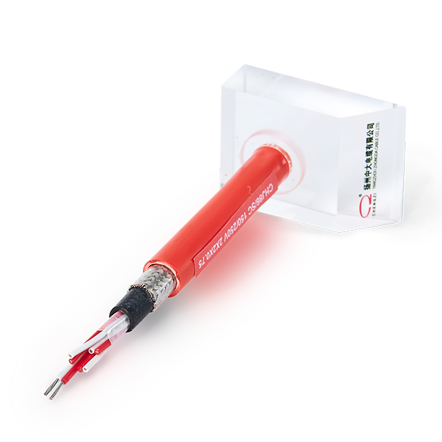
These sensitive lines typically carry a rating of 150/250V. Some standards allow up to 300V. You rely on them for Fieldbus networks, PLC control cards, alarm systems, and Ethernet setups (CAT5/6/7). Because they manage data rather than heavy power loads, their primary design focus leans toward signal integrity. They require excellent shielding against electromagnetic interference (EMI) generated by nearby heavy machinery.
As vessels electrify, higher capacities become necessary. Medium voltage cables range from 1.8/3 kV up to 18/30 kV. High voltage variants can reach up to 150kV. Offshore platforms, electric propulsion vessels, and subsea tie-backs heavily depend on these specialized lines. They require meticulous termination procedures and highly specialized insulation layers to prevent corona discharge.
Table 1: Marine Cable Voltage Application Summary | |||
Application Category | Typical Voltage Rating | Common Use Cases | Key Technical Requirement |
|---|---|---|---|
Low Voltage (LV) Power | 0.6/1 (1.2) kV | Generators, engine feeds, heavy motors | Proper armour earthing for EMF |
Instrumentation & Data | 150/250V (up to 300V) | Fieldbus, PLCs, Ethernet (CAT5/6/7) | EMI shielding for signal integrity |
Medium/High Voltage (MV/HV) | 1.8/3 kV to 150kV | Electric propulsion, subsea tie-backs | Advanced corona discharge prevention |
The electrical architecture of the vessel directly dictates the required insulation level of your chosen wiring. Purchasing standard cables without verifying your specific system architecture risks catastrophic insulation failure. You must understand two primary configurations to evaluate risks properly.
Earthed Systems (100% Insulation Level): In setups featuring a solid connection to earth, the standard Uo/U rating applies directly. When a ground fault occurs, the system immediately trips the circuit breaker to halt the current. This rapid disconnect means the cable insulation never faces sustained overvoltage conditions. You can confidently rely on standard 100% insulation ratings here.
Unearthed Systems (133% Insulation Level): Critical shipboard environments frequently utilize unearthed networks. They allow navigation or propulsion operations to continue safely during a single ground fault. However, this operational resilience creates a unique stress on the wiring. A fault causes the remaining healthy phases to carry the full line-to-line voltage to ground. Consequently, the cable's Uo rating must be scaled up to equal the phase-to-phase voltage. For instance, a 10kV unearthed system requires a 10/15kV rated cable.
Note: Watch out for regional terminology differences. North American specifications frequently refer to a "133% insulation level," while European standards simply dictate "Unearthed systems."
A cable rated for a specific voltage will only deliver that potential effectively if its conductor size mitigates electrical resistance over distance. Cables essentially act as inefficient heaters. Their external insulation serves as a thermal barrier, trapping electrical heat inside the core.
You must adhere to strict ABYC voltage drop standards when sizing conductors for shipboard environments.
Critical Loads (3% max drop): Devices essential for vessel safety fall into this tier. Examples include navigational lights, bilge pumps, and primary communications electronics. To maintain a maximum 3% drop, you usually need thicker conductors, especially for longer wiring runs across the hull.
Non-Critical Loads (10% max drop): Convenience devices allow more sizing flexibility. Cabin lighting, livewell pumps, and ventilation fans can safely operate with up to a 10% voltage drop without compromising safety.
Chart 1: ABYC Voltage Drop Guidelines | |||
Load Type | Max Allowed Drop | Example Equipment | Sizing Implication |
|---|---|---|---|
Critical Safety | 3% | Bilge pumps, nav lights, VHF radios | Requires significantly thicker wire gauges (AWG) |
Non-Critical | 10% | Cabin fans, interior LEDs, livewell pumps | Permits standard gauge sizes for cost efficiency |
Beyond simple voltage drop, you must account for thermal derating. If you bundle multiple Marine Cable runs together or install them in high-temperature engine rooms, ambient heat prevents natural heat dissipation. You must mathematically derate the nominal current capacity. Failing to derate the ampacity risks melting the 90°C or 105°C insulation. This melting compromises the stated voltage rating and invites severe electrical fires.
Evaluating a vendor’s voltage claims requires digging into underlying testing standards and certifications. Use the following logic to validate procurement choices and ensure long-term maritime safety.
Standard Alignment: Verify that the insulation thickness and applied voltage tests strictly conform to international frameworks. The primary benchmarks are IEC 60092-351 for core insulation and IEC 60092-359 for outer sheathing.
Material Verification: Confirm the use of Type III fine-stranded tinned copper. Products meeting UL 1426 guidelines are ideal for flexible installations. Naked copper oxidizes rapidly in humid, salty maritime environments. This localized corrosion increases electrical resistance and causes unexpected voltage drops over time.
Class Society Approvals: Voltage ratings mean little without rigorous third-party verification. Ensure independent marine classification bodies validate the manufacturer specifications. Look for official stamps from DNV-GL, ABS, Lloyd’s Register (LR), or Bureau Veritas (BV). Installing uncertified cables poses a direct, severe liability during official vessel inspections or insurance claims.
The voltage rating of a marine electrical cable represents a highly complex metric. Most commonly sitting at 0.6/1 kV for low-voltage power, this number defines continuous operation limits. It also dictates system architecture compatibility, particularly concerning earthed versus unearthed layouts. Understanding these factors provides essential safety margins that prevent insulation breakdowns and onboard fires.
Before making a procurement decision, consult the vessel's single-line electrical diagram to confirm nominal operating voltages. Next, cross-reference necessary Class Approvals for your specific operating region to guarantee compliance. Finally, always calculate the expected voltage drop based on the total round-trip cable length. Taking these proactive steps ensures a robust, certified, and safe maritime installation.
A: No. While the voltage requirement is low, automotive cables lack independent tinned copper strands and robust marine insulation. They will corrode quickly in salty environments, leading to high resistance, severe voltage drops, and potential electrical fires.
A: Cables are typically rated in AC RMS. For DC systems (common in marine solar, battery banks, and off-grid setups), the equivalent DC voltage tolerance is generally higher than the stated AC RMS rating (often 1.5 times the AC Uo rating). Always consult the manufacturer's datasheet for specific DC tolerances.
A: Yes, provided the cables are rated for the system's maximum voltage. High-capacity lithium systems require strictly calculated conductor sizes (often 4/0 AWG or larger) to handle high continuous amp draws with minimal voltage drop.
 简体中文
简体中文 

