

Views: 0 Author: Site Editor Publish Time: 2026-10-21 Origin: Site


The unforgiving maritime environment relentlessly attacks weak electrical systems. Deep within a vessel's engine room, the constant thrum of heavy machinery, salt-laden moisture, and extreme temperature fluctuations test every component to its absolute limit. In this harsh setting, installing a marine VFD cable incorrectly does not just cause severe motor failures. It unleashes dangerous electromagnetic interference that can blind critical navigation arrays and dynamic positioning systems. Throughout this guide, we will explore the nuances of proper routing and termination. Furthermore, we will dive into the essential grounding techniques required to maintain absolute shipboard safety and operational uptime.
Specialized Construction: A standard marine power conductor lacks the heavy shielding required to handle high-frequency noise and voltage spikes generated by Variable Frequency Drives. A dedicated VFD conductor is an absolute engineering requirement.
Proper Termination is Crucial: Incorrectly terminating the cable shield, specifically through the lazy practice of pigtailing, is the primary cause of Electromagnetic Interference and premature motor bearing failure in shipboard applications.
Safety First: Maritime installations must utilize a Low Smoke Zero Halogen jacket to comply with international safety standards like ABS and DNV. This critical feature protects the crew from toxic halogen gases during enclosed shipboard fires.
Symmetrical Grounding: Utilizing cables engineered with three symmetrical ground wires effectively cancels out common-mode currents. This prevents rogue electrical noise from destabilizing the vessel's broader electrical grid.
A review of recent maritime engineering developments reveals a massive shift in how classification societies view electrical installations. Modern vessels are highly digitized. They rely on automated dynamic positioning systems, delicate IoT engine sensors, and complex digital bridge networks. Consequently, the industry tolerance for electromagnetic noise has plummeted to near zero. Marine surveyors and auditors are noticeably tightening their inspection criteria. Proper cable selection and strict routing separation are no longer just recommended best practices. They are heavily scrutinized compliance mandates designed to prevent catastrophic digital blackouts while at sea.
Understanding the fundamental differences in cable construction is the first step toward a successful installation. Marine environments are demanding by default. However, introducing a variable frequency drive adds complex electrical stresses that standard wiring simply cannot survive. High-frequency switching creates harsh voltage reflections that tear through weak insulation.
A purpose-built inverter cable is engineered with specific components designed to mitigate the unique electrical phenomena created by modern drives. Specifically, the insulation relies on heavy-wall Cross-Linked Polyethylene, widely known as XLPE. Unlike standard PVC, XLPE boasts exceptional dielectric strength. It easily withstands the extreme voltage spikes and corona discharges associated with rapid switching frequencies, maintaining integrity even at 90 degrees Celsius operating temperatures.
In addition, the shielding system is highly specialized. A premium marine VFD line utilizes a dual-shielding design. This typically combines an overlapping copper tape with a tightly woven tinned copper braid that provides over 85 percent coverage. This robust combination creates a continuous Faraday cage around the inner conductors, permanently trapping high-frequency noise. Finally, the internal geometry features a symmetrical ground design. Three ground wires sit evenly in the interstices of the three phase conductors, ensuring a perfectly balanced magnetic field.
Engineers often question whether a standard Marine Power Cable can be repurposed for drive applications to save upfront costs. The empirical answer from veteran pump and motor engineers is absolutely not. Standard power conductors are designed strictly for 50 or 60 Hertz sinusoidal power transmission. When subjected to the high-frequency, pulse-width modulated signals of a drive, standard cables fail completely. They cannot contain the resulting electromagnetic noise and degrade rapidly under intense voltage reflections.
Feature | Standard Marine Power Cable | Dedicated Marine VFD Cable |
|---|---|---|
Insulation Material | Standard PVC or basic EPR | Heavy-wall XLPE rated for 1.8/3kV (High dielectric strength) |
Shielding Design | Unshielded or single basic braid | Dual shield featuring Copper tape plus Tinned copper braid |
Grounding Configuration | Single offset ground conductor | Three symmetrical ground conductors for magnetic balance |
EMI Containment | Minimal to None | Exceptional containment preventing cross-talk with ship sensors |
Voltage Spike Tolerance | Low threshold susceptible to corona breakdown | High threshold engineered for reflected wave phenomena |
Improper cable selection directly leads to degraded motor performance, frequent drive overcurrent faults, and the eventual catastrophic dielectric breakdown of the cable insulation.
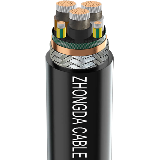
Before pulling any wire through a vessel's cramped bulkheads, procurement officers and marine electricians must ensure the selected cable meets exact technical and regulatory requirements. An installation is only as reliable as the materials specified during the planning phase.
Sizing a drive cable requires far more than simply checking the motor full-load amperage. The rapid switching of Insulated-Gate Bipolar Transistors inside the drive creates high-frequency harmonic currents. These harmonics cause the skin effect, where current is violently forced to the outer surface of the conductor. This effectively increases the overall cable resistance and generates excess heat.
Consequently, engineers must calculate the correct gauge based on the motor size, the continuous output capacity of the drive, and the total length of the cable run. Longer cable runs increase parasitic capacitance. This exacerbates voltage drop and reflected wave phenomena. If the cable run exceeds the manufacturer recommended maximum length, load reactors or specialized filters must be integrated into the system design to protect the delicate motor windings from voltage spikes.
Shipboard environments are heavily regulated by international classification societies. It is critical to select a Shipboard VFD Cable that explicitly carries certifications from governing bodies such as the American Bureau of Shipping or Det Norske Veritas. Look for cables that comply with IEC 60092 standards. These certifications guarantee that the cable has passed rigorous testing for intense vibration, salt-water moisture resistance, and flame retardancy.
Additionally, enclosed marine spaces require strict adherence to fire safety protocols. Specifying a Low Smoke Zero Halogen jacket is absolutely vital. In the terrifying event of an engine room fire, standard PVC jackets release thick, blinding black smoke and highly corrosive halogen gases. In stark contrast, certified halogen-free cables emit minimal smoke and zero toxic acids. This ensures better visibility for crew evacuation and prevents corrosive acid damage to the ship's expensive navigational electronics.
Routing cables through a ship requires meticulous planning. The physical layout of the cable tray directly impacts the electromagnetic compatibility of the entire vessel.
Vessels are notoriously cramped, requiring cables to navigate tight corners and complex bulkhead penetrations. However, drive cables have strict minimum bending radius requirements. These typically range from 12 to 15 times the overall outer diameter of the cable.
If an installer bends a cable beyond this minimum radius, the internal geometry is physically crushed. The overlapping copper tape shield can buckle, tear, or separate. This creates a physical gap in the Faraday cage. That tiny gap acts as a radiating antenna, broadcasting high-frequency noise directly into the surrounding environment. Installers must use proper cable pulling tools, generous amounts of pulling lubricant, and wide-angle cable tray fittings to ensure the bend radius is respected throughout the entire run.
To maintain clean power across the vessel, installers must strictly follow the Free Space rule. Drive cables carry electrically noisy signals and must never be routed in the same tray as low-voltage control cables, ethernet communication lines, or standard power cables.
Industry best practices dictate maintaining a minimum separation distance of 300 millimeters between high-power lines and sensitive data networks. If a drive cable must cross paths with a communication wire, they should intersect at a precise 90-degree angle to minimize magnetic cross-talk. Furthermore, these high-power cables should be laid flat in the cable tray rather than bundled tightly together with zip ties. Laying them flat allows for adequate heat dissipation and drastically reduces capacitive coupling between multiple drive systems.
Grounding a variable frequency system is fundamentally different from grounding a standard utility power circuit. In standard electrical systems, grounding is primarily designed for personnel safety and clearing short circuits. However, in a drive system, grounding serves as a highly engineered path for managing high-frequency noise.
When a drive pulses voltage to control motor speed, it inadvertently creates common-mode voltage. Because the motor stator is capacitively coupled to the motor frame, this voltage induces high-frequency common-mode currents. These stray currents aggressively seek a path back to the drive. If the Inverter Cable shield does not provide a low-impedance return path, these currents will travel through the ship hull, grounding grids, and ultimately arc through the motor bearings.
The shield of the cable is explicitly designed to act as this controlled, low-impedance return path. By keeping the high-frequency noise contained within the metallic cable structure, it prevents parasitic currents from wreaking havoc on the vessel radar, sonar, and dynamic positioning arrays.
To effectively manage these currents, the industry standard is unequivocal. The shield of the cable must be grounded at both the motor end and the drive end. Grounding at only one end is a dangerous, outdated misconception inherited from legacy analog systems. Leaving one end floating renders the shield entirely useless for high-frequency noise containment.
Furthermore, the grounding must utilize a full 360-degree contact method. When using a symmetrical cable featuring three phase conductors and three ground conductors, the three ground wires must be terminated evenly to the ground busbar. This symmetrical arrangement ensures that the magnetic fields generated by the ground currents perfectly cancel each other out. This drastically reduces the overall net magnetic emissions radiating from the cable.
Termination is the most critical phase of the installation. A flawless, perfectly routed cable pull can be entirely ruined by a sloppy termination at the drive or motor junction box. The following standard operating procedure outlines the correct method for terminating shielded cables from an engineer's perspective.
Precision is paramount when preparing the conductor ends. Installers must use specialized rotary stripping tools to remove the outer jacket without scoring or nicking the underlying copper tape or tinned braid. Even a microscopic scratch on the shield can compromise its integrity and leak noise.
Measure the required length for the phase conductors to reach the terminals comfortably. Allow for a gentle sweeping bend rather than a sharp, stressful angle.
Carefully score the outer jacket and peel it back smoothly.
Expose the woven braid and copper tape. Specifically, do not cut the shield back flush to the jacket edge. A sufficient length of the shield must be left exposed to make full 360-degree contact with the grounding hardware.
The most common and destructive mistake made during termination is pigtailing the shield. Pigtailing involves twisting the copper braid into a single wire and terminating it to a standard ground lug. At high frequencies, a pigtail creates massive electrical inductance, acting as a severe bottleneck. The high-frequency noise will reject this high-impedance path. Instead, it will discharge through the motor bearings or radiate into the environment.
Instead, installers must use proper Electromagnetic Compatibility cable glands or saddle clamps. These specialized metallic devices clamp firmly around the entire circumference of the exposed shield. This provides a full 360-degree, ultra-low-impedance connection directly to the grounded metal enclosure of the drive and the motor terminal box.
Once the shield is properly secured via a metal gland, the individual conductors can be safely terminated.
Strip the XLPE insulation from the phase conductors. Ensure absolutely no copper strands are severed in the process, as this reduces the ampacity of the wire.
Apply the correct size ring terminals or ferrules using a calibrated crimping tool to ensure a gas-tight connection.
Terminate the three symmetrical ground wires to the designated ground bus or chassis lug. Ensure they are spaced evenly if multiple lugs are available to maintain magnetic balance.
Finally, use a calibrated torque wrench to tighten all connections to the manufacturer exact specifications. Under-torqued connections cause arcing and overheating, while over-torqued connections can crush and sever the delicate copper strands.
Before applying live power to the newly installed system, rigorous testing must be conducted to verify the integrity of the cable and the terminations. Skipping this vital step can result in immediate drive destruction upon startup.
The primary verification method is an Insulation Resistance test, commonly known as a megohmmeter test. This verifies that the heavy-wall XLPE insulation was not scraped, crushed, or compromised during the strenuous cable pulling process.
The cable must be completely disconnected from both the drive and the motor before testing. Applying high test voltages to a connected drive will permanently destroy its internal microprocessors and delicate transistors.
Test the resistance between each phase conductor, and between each phase conductor and the ground shield. For standard 480-volt or 600-volt marine systems, a 1000-volt DC test voltage is typically applied. The resulting resistance should read in the high megaohms or gigaohms. Any low reading indicates a tear in the insulation or a dead short circuit that must be rectified immediately before powering the system.
If a vessel experiences electrical anomalies after an installation, the cabling is the very first system to investigate. Below is a diagnostic reference for common symptoms caused by improper cable installation:
Symptom or Anomaly | Likely Cable Installation Fault |
|---|---|
Premature Motor Bearing Failure | Shield improperly terminated via pigtailing or grounded at only one end. Common-mode currents are discharging through the bearings, causing electrical pitting. |
Erratic Ship Sensor Data | Cable routed too closely to data cables, violating the Free Space rule. Noise is cross-talking into low-voltage lines. |
Drive Overcurrent on Startup | Insulation damaged during installation due to exceeded bend radius, causing a phase-to-ground short. Alternatively, the cable run is excessively long. |
By systematically verifying the routing, ensuring 360-degree shield termination, and confirming insulation integrity, marine engineers can isolate and resolve these issues swiftly.
Installing variable speed equipment on a vessel is a highly unforgiving process. The harsh realities of the maritime environment, combined with the complex electrical physics of pulse width modulation, mean that minor installation errors can snowball into catastrophic system failures. Below is a detailed technical analysis of the most frequent errors made by inexperienced installers.
One of the most destructive errors in maritime electrical engineering is substituting a specialized inverter conductor with a standard power cable to artificially reduce upfront procurement costs. A standard power conductor is exclusively engineered to transmit clean alternating current at low frequencies. However, modern drives simulate an AC waveform through incredibly rapid switching.
This rapid switching generates steep voltage rise times. When these high-frequency pulses travel down a standard unshielded cable, they encounter impedance mismatches at the motor terminals. This causes the voltage pulses to reflect back toward the source, compounding with incoming pulses to create severe voltage overshoots. Over time, this intense electrical stress breaks down standard PVC insulation, resulting in catastrophic short circuits. To prevent this, a dedicated cable featuring high-dielectric XLPE insulation is strictly required.
Ignoring fire safety ratings in enclosed shipboard environments is a critical regulatory violation. Maritime classification societies mandate stringent fire safety protocols for all materials installed below deck. Standard industrial cables often utilize Polyvinyl Chloride jackets because of their cost-effectiveness. However, these materials present a lethal hazard during a thermal event on a vessel.
When exposed to direct flame, standard jackets undergo rapid thermal degradation. They release thick, opaque black smoke that instantly reduces visibility to zero. Furthermore, the combustion produces highly toxic and corrosive acid gases that destroy printed circuit boards and dynamic positioning systems. Specifying a certified Low Smoke Cable ensures compliance with IEC 60332-3 standards. These advanced materials emit minimal, translucent smoke and zero corrosive gases, preserving human life and protecting critical shipboard infrastructure.
Grounding the cable shield at only one end is a pervasive error inherited from legacy analog instrumentation practices. In low-voltage analog applications, grounding a shield at a single point is acceptable to prevent low-frequency ground loops. However, modern drive systems operate entirely in the high-frequency domain.
If the shield is grounded at the drive end but left floating at the motor end, the ungrounded portion of the shield acts as a massive radiating antenna. This ungrounded antenna broadcasts severe noise throughout the vessel structure, disrupting sensitive communication arrays. Additionally, without a continuous shield connection, common-mode currents will seek the path of least resistance back to the source. This path is almost always through the motor bearings, leading to premature bearing fluting and ultimate motor failure.
Routing a high-power run tightly bundled with low-voltage communication lines violates fundamental electromagnetic compatibility principles. The high-frequency harmonic noise generated by the drive generates expanding, oscillating electromagnetic fields around the cable trajectory.
When sensitive data lines, such as Ethernet cables or marine network lines, are routed in close physical proximity to the power run, these magnetic fields induce unwanted transient voltages into the data cables. This inductive crosstalk leads to erratic sensor readings and unpredictable control system behavior. To prevent this, marine electricians must adhere to strict spatial separation, maintaining a generous physical distance between power and control lines.
Installing a shipboard drive cable correctly demands strict precision, deep technical knowledge, and unwavering care. You must follow proper routing rules and maintain mandatory separation distances to prevent digital interference across the ship. Always select certified, flame-retardant materials designed specifically for the punishing marine environment. Furthermore, executing proper 360-degree termination prevents costly motor bearing failures and highly dangerous electrical hazards. High-quality cables, when installed correctly, ensure your vessel operates safely and efficiently. Invest in reliable infrastructure and rigorous installation practices to protect your maritime operations from unexpected, catastrophic downtime. For certified, high-performance solutions that meet global maritime standards, explore the extensive catalog at ZD Cables to find the exact engineering match for your next shipboard project.
No, utilizing standard power conductors for variable frequency applications is strongly prohibited by modern marine engineering standards. Standard power cables are structurally designed for low-frequency sinusoidal waveforms. They lack the necessary XLPE insulation thickness and dielectric properties to withstand the severe voltage spikes and corona discharge generated by rapid pulse width modulation. Furthermore, standard cables do not possess the comprehensive copper tape and braided shielding required to contain high-frequency noise. Using them will inevitably lead to premature insulation degradation, catastrophic motor bearing damage, and widespread electrical interference across the vessel grid.
Proper termination dictates the effectiveness of the entire shielding architecture. A common, yet highly destructive error is pigtailing the copper shield. This involves twisting the braided shield into a single wire and connecting it to a standard ground lug. At high frequencies, the skin effect causes a pigtail to act as an inductor, creating massive electrical impedance. This impedance blocks common-mode currents from returning safely to the drive, forcing them to find alternative paths through the ship hull or the motor bearings. Utilizing proper 360-degree metal cable glands ensures a continuous, ultra-low impedance connection, allowing the shield to effectively contain and route high-frequency noise.
Yes, grounding both ends is an absolute requirement for all modern installations. While legacy analog systems grounded only one end to prevent low-frequency ground loops, modern drives generate high-frequency noise that behaves according to different physical laws. The shield must be firmly bonded at both the drive enclosure and the motor terminal box to create a complete Faraday cage effect. This 360-degree containment prevents the cable from acting as an antenna and broadcasting interference. The inherent equipotential bonding grid of the vessel ensures that grounding both ends does not create hazardous low-frequency ground loops.
Shipboard environments are highly confined enclosed spaces where air circulation is strictly controlled and evacuation routes are limited. In the event of an electrical fire, standard PVC-jacketed cables release thick, blinding black smoke and highly toxic halogen gases. These gases mix with ambient moisture to form corrosive acids that permanently destroy critical navigation, communication, and control electronics. A halogen-free cable is manufactured from specialized thermoplastic polymers. When exposed to flame, they emit minimal, translucent smoke and zero corrosive gas, ensuring crew visibility during evacuation and protecting the surviving ship infrastructure.
The maximum allowable length depends heavily on the specific drive manufacturer engineering specifications and the internal capacitance of the cable. Extended cable runs exacerbate the reflected wave phenomenon, a transmission line effect where voltage pulses reflect off the motor terminals and compound with incoming pulses. This compounding can result in peak voltages exceeding 1,500 volts on a standard 480-volt system, which rapidly destroys motor winding insulation. As a general engineering rule, runs exceeding 50 meters require careful mathematical evaluation. If long runs are unavoidable due to the physical layout of the vessel, engineers must install load reactors or specialized filters at the drive output to smooth the waveform and protect the motor.
While a standard shielded cable offers basic protection against low-frequency signal interference, a dedicated marine VFD cable is vastly superior in construction. Standard shielded cables typically use a thin foil or a loose copper braid and rely on standard PVC insulation. In contrast, a true VFD cable utilizes a robust dual-shielding system combining heavy overlapping copper tape with a dense tinned copper braid for maximum high-frequency containment. Additionally, it features heavy-wall XLPE insulation designed specifically to withstand the aggressive voltage spikes and thermal stresses produced by variable frequency drives, along with specialized symmetrical ground wires to balance magnetic fields.
Proper testing requires an insulation resistance test using a megohmmeter. Before testing, it is absolutely critical to physically disconnect the cable from both the variable frequency drive and the motor. Applying high test voltages to a connected drive will instantly destroy its internal electronics. Once disconnected, technicians apply a high DC voltage, typically 1000 volts for standard marine systems, between the phase conductors and between each phase and the ground shield. The resistance readings should be exceptionally high, usually in the gigaohm range. Any low reading indicates that the cable jacket or insulation was damaged during the pulling process and must be repaired or replaced before startup.
 简体中文


